Installation/ Operator Maintenance VariTrane™ Single-Duct and Fan-Powered Units All VariTrane VAV Models with pneumatic, electronic, DDC controls and diffusers.
© 2006 American Standard All rights reserved VAV-SVN01E-EN
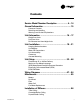
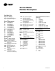
Contents Service Model Number Description .................. 4 – 14 General Information ............................................... 15 Literature Contents Receiving and Handling Warnings and Cautions Explanations Unit Information ............................................. 16 – 17 Single-Duct Units Dual-Duct Units Fan-Powered and Low-Height Units Unit Installation ..............................................
Service Model Number Description WARNING Fiberglass Wool! WARNING: ALL INSULATED UNITS (except closed-cell foam insulation) CONTAIN FIBERGLASS WOOL! Read this literature prior to installation for proper instruction. Disturbing the insulation in this product during installation, maintenance or repair will expose you to airborne particles of glass wool fibers and ceramic fibers known to the state of California to cause cancer through inhalation.
Service Model Number Description Single-Duct Units (con't.) Digit 17—Not Used 0 N/A Digit 18—Not Used 0 N/A Digit 19—Outlet Plenum (Connection is Slip & Drive) 0 None A 1 Outlet RH B 1 Outlet END C 1 Outlet LH D 2 Outlets, 1 RH, 1 END E 2 Outlets, 1 LH, 1 END F 2 Outlets, 1 RH, 1 LH H 3 Outlets, 1 LH, 1 RH, 1 END J 4 Outlets, 1 LH, 1 RH, 2 END Note: See unit drawings for outlet sizes/ damper information.
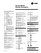
Service Model Number Description Dual-Duct Units Digit 1, 2, 3—Unit Type VDD VariTrane dual-duct Digit 4—Development Sequence F Sixth Digit 5, 6—Primary Air Valve 05 5" inlet (350 cfm) 06 6" inlet (500 cfm) 08 6" inlet (900 cfm) 10 10" inlet (1400 cfm) 12 12" inlet (2000 cfm) 14 14" inlet (3000 cfm) 16 16" inlet (4000 cfm) Digit 7, 8—Secondary Air Valve 05 5" inlet (350 cfm) 06 6" inlet (500 cfm) 08 8" inlet (900 cfm) 10 10" inlet (1400 cfm) 12 12" inlet (2000 cfm) 14 14" inlet (3000 cfm) 16 16" inlet (400
Service Model Number Description Fan-Powered Parallel Units Digit 1, 2—Unit Type VP VariTrane fan-powered parallel Digit 3—Reheat C Cooling Only E Electric Heat W Hot Water Heat Digit 4—Development Sequence F Sixth Digit 5, 6—Primary Air Valve 05 5" inlet (350 max cfm) 06 6" inlet (500 max cfm) 08 8" inlet (900 max cfm) 10 10" inlet (1400 max cfm) 12 12" inlet (2000 max cfm) 14 14" inlet (3000 max cfm) 16 16" inlet (4000 max cfm) Digit 7, 8—Secondary Air Valve 00 N/A Digit 9—Fan P 02SQ fan (500 nominal cfm
Service Model Number Description Fan-Powered Parallel Units (con't) Digit 30—Electric Heat Stages 0 None 1 1 Stage 2 2 Stages Equal 3 3 Stages Equal Digit 31—Contactors 0 None 1 24-volt magnetic 2 24-volt mercury 3 PE with magnetic 4 PE with mercury Digit 32—Airflow Switch 0 None W With 8 VAV-SVN01E-EN
Service Model Number Description Fan-Powered Series Units Digit 1, 2—Unit Type VS VariTrane fan-powered series Digit 3—Reheat C Cooling Only E Electric Heat W Hot Water Heat Digit 4—Development Sequence F Sixth Digit 5, 6—Primary Air Valve 04 4" inlet (225 max cfm) 05 5" inlet (350 max cfm) 06 6" inlet (500 max cfm) 08 8" inlet (900 max cfm) 10 10" inlet (1400 max cfm) 12 12" inlet (2000 max cfm) 14 14" inlet (3000 max cfm) 16 16" inlet (4000 max cfm) Digit 7, 8—Secondary Air Valve 00 N/A Digit 9—Fan P 02S
Service Model Number Description Fan-Powered Series Units (con't) Digit 27, 28, 29—Electric Heat Kilowatts 000 None 050 0.5 kW 010 1.0 kW 015 1.5 kW 240 24.
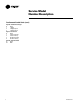
Service Model Number Description Fan-Powered Low-Height Parallel Units Digit 1, 2—Unit Type LP VariTrane fan-powered lowheight parallel Digit 3—Reheat C Cooling Only E Electric Heat W Hot Water Heat Digit 4—Development Sequence F Sixth Digit 5, 6—Primary Air Valve 05 5" inlet (350 maximum cfm) 06 6" inlet (500 maximum cfm) 08 8" inlet (900 maximum cfm) RT 8" x 14" inlet (1800 maximum cfm) Digit 7, 8—Secondary Air Valve 00 N/A Digit 9—Fan V 08SQ 500 nominal cfm W 09SQ 900 nominal cfm X 10SQ 1800 nominal cfm
Service Model Number Description Fan-Powered Low-Height Parallel Units (con't) Digit 27, 28, 29—Electric Heat Voltage 000 None 005 0.5 kW 010 1.0 kW 015 1.5 kW 020 2.0 kW 025 2.5 kW 030 3.0 kW 035 3.5 kW 040 4.0 kW 045 4.5 kW 050 5.0 kW 055 5.5 kW 060 6.0 kW 065 6.5 kW 070 7.0 kW 075 7.5 kW 080 8.0 kW 090 9.0 kW 100 10.0 kW 110 11.0 kW 120 12.0 kW 130 13.0 kW 140 14.
Service Model Number Description Fan-Powered Low-Height Series Units Digit 1, 2—Unit Type LS VariTrane low-height series fanpowered Digit 3—Reheat C Cooling Only E Electric Heat W Hot Water Heat Digit 4—Development Sequence F Sixth Digit 5, 6—Primary Air Valve 05 5" inlet (350 cfm) 06 6" inlet (500 cfm) 08 8" inlet (900 cfm) RT (8" x 14" inlet (1800 cfm) Digit 7, 8—Secondary Air Valve 00 N/A Digit 9—Fan V 08SQ 500 nominal cfm W 09SQ 900 nominal cfm X 10SQ 1800 nominal cfm Digit 10, 11—Design Sequence K0 Si
Service Model Number Description Fan-Powered Low-Height Series Units (con't) Digit 27, 28, 29—Electric Heat Voltage 000 None 005 0.5 kW 010 1.0 kW 015 1.5 kW 020 2.0 kW 025 2.5 kW 030 3.0 kW 035 3.5 kW 040 4.0 kW 045 4.5 kW 050 5.0 kW 055 5.5 kW 060 6.0 kW 065 6.5 kW 070 7.0 kW 075 7.5 kW 080 8.0 kW 090 9.0 kW 100 10.0 kW 110 11.0 kW 120 12.0 kW 130 13.0 kW 140 14.0 kW 150 15.0 kW 160 16.0 kW 170 17.0 kW 180 18.
General Information Literature Contents This manual describes the installation of VariTrane VAV units with recommended wiring, piping, and mounting of Single-Duct, Dual-Duct, Fan-Powered, Low-Height terminal units and diffusers. Receiving and Handling VariTrane Units are shipped completely assembled with the exceptions of optional attenuators for fan-powered units and accessories.
Unit Information Single-Duct Units The basic unit consists of a sheet metal casing with an air valve, which is used to modulate the air being delivered into the occupied zone.The unit is designed to modulate either cooling or heating air between the temperatures of 40°F and 140°F.
Unit Information Fan-Powered and Fan-Powered Low-Height Units VariTrane fan-powered and low-height fan-powered units can be either parallel or series, with or without re-heat. (See Figure 3.) The fan on a series unit runs continuously whenever the main air handler unit is in operation.There are various options for starting the fan.The fan can be started three ways: 1) remotely, 2) by a duct pressure switch, or 3) by a combination of both.
Unit Installation Due to their weight, the VAV terminal units should be suspended from the uppermost ceiling, independent of the false ceiling grid. Suspension devices are to be supplied by the installer. Units must be installed level and upright. Failure to level the unit properly may prevent proper operation of the controls and/or terminal unit. Units are not designed to be installed vertically. Consequently, this will also void the UL ratings and any warranty on the unit.
Unit Installation Fan-Powered (Standard and LowHeight) Fan-powered units should be supported by either hanger straps or by using a threaded rod in conjunction with the hanger brackets that are provided on the unit. Care should be exercised to insure that the hanging straps do not block the side access panel. See Figures 6–13.
Unit Installation Figure 7 Series Hanger Bracket Locations A Flow Ring Tubing B C Air Valve Optional Attenuator Field Installed Airflow Plenum Inlet TOP VIEW Series Cooling & Hot Water E D 2. 1. Fan Inlet w/o Attenuator 1. All attenuators are the same length and width. 2. Sizes 01 and 02 units are smaller than attenuators. Water Coil 1.625" (41 mm) FAN SIZE A B C D E F (Elec. Heat Only) 20.132" (511 mm) 02SQ 18.75" (476 mm) 26.75" (679 mm) 3.25" (83 mm) 41.154" (1041 mm) 35.
Unit Installation Figure 8 Low-Height Parallel 08SQ/09SQ w/ Hot Water or Electric Heat 31.65" (804 mm) 13.00" (330 mm) Airflow Plenum Inlet 23.90" (607 mm) Primary Airflow 19.86" (504 mm) Optional Attenuator Field Installed 24.30" (617 mm) 3.35" (85 mm) Airflow Discharge Outlet 23.10" (587 mm) 13.80" (350 mm) TOP VIEW 4.00" (102 mm) 31.65" (804 mm) 13.00" (330 mm) 23.90" (607 mm) Airflow Plenum Inlet Primary Airflow 19.86" (504 mm) Optional Attenuator Field Installed Terminal Box 24.
Unit Installation Figure 9 Low-Height Parallel10SQ 1.625" (41 mm) Flow Ring Tubing 38.95" (989 mm) Primary Airflow Plenum Inlet Air Valve 5.625" (143 mm) 38.75" (984 mm) Terminal Box Optional Heater 5.625" (143 mm) Airflow Discharge Outlet 41.
Unit Installation Figure 10 Low-Height Series 08SQ/09SQ w/ Hot Water or Electric Heat 31.65" (804 mm) 4.00" (102 mm) 10.13" (257 mm) 12.85" (326 mm) Airflow Plenum Inlet Primary Airflow 19.86" (504 mm) Optional Attenuator Field Installed Air Valve 3.35" (85 mm) 34.30" (871 mm) 31.65" (804 mm) 3.35" (85 mm) Water Coil TOP VIEW 4.00" (102 mm) 10.13" (257 mm) 12.85" (326 mm) Airflow Plenum Inlet Primary Airflow Optional Attenuator Field Installed Air Valve Airflow 19.86" (504 mm) 3.
Unit Installation Figure 11 Low-Height Series 10SQ w/ Hot Water or Electric Heat 19.45" (494 mm) 31.65" (804 mm) 19.45" (494 mm) 10.12" (257 mm) 31.65" (804 mm) Optional Attenuator Field Installed Optional Attenuator Field Installed Primary Airflow 19.86" (504 mm) Airflow Plenum Inlet Airflow Plenum Inlet 3.35" (85 mm) 19.86" (504 mm) 30.30" (770 mm) 3.35" (85 mm) TOP VIEW Airflow Discharge Outlet 3.50" (89 mm) 42.00" (1067 mm) 3.50" (89 mm) 19.45" (494 mm) 31.65" (804 mm) 10.
Unit Installation Figure 12 Attenuator Installation—Parallel Units 1. Attach attenuator to unit as shown with provided mounting brackets. MOUNTING BRACKET OPTIONAL ATTENUATOR FIELD INSTALLED Note: Bottom bracket not shown. Bottom bracket to be installed in same orientation on bottom of unit.
Unit Installation Figure 13 Attenuator Installation—Series Units 1. Attach attenuator to unit as shown with provided mounting brackets. MOUNTING BRACKET OPTIONAL ATTENUATOR FIELD INSTALLED Note: Bottom bracket not shown. Bottom bracket to be installed in same orientation on bottom of unit.
Unit Installation Figure 14 Attenuator Installation—Low-Height Parallel Units 1. Attach attenuator to unit as shown with provided mounting brackets. MOUNTING BRACKET OPTIONAL ATTENUATOR FIELD INSTALLED Note: Bottom bracket not shown. Bottom bracket to be installed in same orientation on bottom of unit.
Unit Installation Figure 15 Attenuator Installation—Low-Height Series Units 1. Attach attenuator to unit as shown with provided mounting brackets. MOUNTING BRACKET OPTIONAL ATTENUATOR FIELD INSTALLED MOUNTING BRACKET OPTIONAL ATTENUATOR FIELD INSTALLED OPTIONAL ATTENUATOR FIELD INSTALLED MOUNTING BRACKET Note: Bottom bracket not shown. Bottom bracket to be installed in same orientation on bottom of unit.
Unit Installation Chart 1 – Unit Weights Single-Duct Units Unit Size VCCF (lbs/kg) VCCF w/ Dual Wall (lbs/kg) 16/7 16/7 16/7 16/7 22/10 27/12 32/15 35/16 52/24 19/9 19/9 19/9 20/9 27/12 34/15 41/19 46/21 63/29 4 5 6 8 10 12 14 16 24 VCEF (lbs/kg) VCEF w/ Dual Wall (lbs/kg) VCWF 1-Row (lbs/kg) VCWF 2-Row (lbs/kg) VCWF 1-Row w/ Dual Wall (lbs/kg) VCWF 2-Row w/ Dual Wall (lbs/kg) 38/17 38/17 38/17 38/17 46/21 52/24 60/27 69/31 84/38 48/22 48/22 48/22 49/22 60/27 68/31 80/36 91/41 106/48 21/10 21
Unit Installation Chart 1 – Unit Weights (Con't.
Unit Installation Duct Connections All VariTrane units should be provided with a minimum of 1.5-duct diameters of straight duct prior to the inlet of the unit. It is recommended that at least 48 inches of straight duct be provided from the discharge of the units prior to any take-offs or transitions. This is a requirement for electric heat fanpowered units used in applications with 100% downward discharge.
Unit Setup Chart 2 – Flow Sensor Delta P vs. Airflow Delivery Flow Sensor Differential Pressure (inches water) 10 6 4 1 8" 10" 8" x 12" 12" 14" 16" 16" x 24" 5 0.1 0.
Unit Setup (SCR) Motor Speed Control Adjustment Procedure. In order to make units more convenient and efficient to balance, an SCR (silicone control rectifier) is provided as standard on all fan-powered units. The SCR is located on the side of the fan control box. To adjust the speed of the motor, the external knob must be rotated either clockwise or counterclockwise depending on the desired speed adjustment.
Unit Setup Chart 4 – VPxF 03SQ ECM CFM Table VPxF 03SQ Motor Min CFM: 160 Motor Max CFM: 1085 CFM L/sec % Setting TENS Switch UNITS Switch CFM % L/sec TENS Setting UNITS Switch Switch 160 170 179 188 198 207 216 226 235 244 254 263 272 282 291 300 310 319 328 338 347 356 366 375 385 394 403 413 422 431 441 450 459 469 478 487 497 506 515 525 534 543 553 562 571 581 590 599 609 618 76 80 84 89 93 98 102 107 111 115 120 124 129 133 137 142 146 151 155 159 164 168 173 177 181 186 190 195 199 204 2
Unit Setup Chart 5 – VPxF 04SQ ECM CFM Table VPxF 04SQ Motor Min CFM: 220 Motor Max CFM: 1510 VAV-SVN01E-EN CFM L/sec % Setting TENS Switch UNITS Switch CFM L/sec % Setting TENS Switch UNITS Switch 220 233 246 259 272 285 298 311 324 337 350 363 376 389 402 415 429 442 455 468 481 494 507 520 533 546 559 572 585 598 611 624 637 650 663 676 689 702 715 728 741 754 767 780 793 806 819 832 845 859 104 110 116 122 128 135 141 147 153 159 165 171 178 184 190 196 202 208 215 221 227 233 239 245 251
Unit Setup Chart 6 – VPxF 05SQ ECM CFM Table VPxF 05SQ Motor Min CFM: 280 Motor Max CFM: 1850 CFM % L/sec Setting TENS Switch UNITS Switch CFM L/Sec % Setting TENS Switch UNITS Switch 280 296 312 327 343 359 375 391 407 423 438 454 470 486 502 518 534 549 565 581 597 613 629 645 661 676 692 708 724 740 756 772 787 803 819 835 851 867 883 898 914 930 946 962 978 994 1009 1025 1041 1057 132 140 147 155 162 170 177 184 192 199 207 214 222 229 237 244 252 259 267 274 282 289 297 304 312 319 327 334
Unit Setup Chart 7 – VPxF 06SQ ECM CFM Table VPxF 06SQ Motor Min CFM: 530 Motor Max CFM: 2100 VAV-SVN01E-EN CFM % L/sec TENS Setting UNITS Switch Switch CFM L/sec % Setting TENS Switch `UNITS Switch 530 546 562 577 593 609 625 641 657 673 688 704 720 736 752 768 784 799 815 831 847 863 879 895 911 926 942 958 974 990 1006 1022 1037 1053 1069 1085 1101 1117 1133 1148 1164 1180 1196 1212 1228 1244 1259 1275 1291 1307 250 258 265 273 280 287 295 302 310 317 325 332 340 347 355 362 370 377 385 39
Unit Setup Chart 8 – VSxF 03SQ ECM CFM Table VSxF 03SQ Motor Min CFM: 200 Motor Max CFM: 1100 CFM L/sec % Setting TENS Switch UNITS Switch CFN % L/sec TENS Setting UNITS Switch Switch 200 209 218 227 236 246 255 264 273 282 291 300 309 318 327 336 346 355 364 373 382 391 400 409 418 427 436 446 455 464 473 482 491 500 509 518 527 536 546 555 564 573 582 591 600 609 618 627 636 646 94 99 103 107 112 116 120 124 129 133 137 142 146 150 154 159 163 167 172 176 180 185 189 193 197 202 206 210 215 2
Unit Setup Chart 9– VSxF 04SQ ECM CFM Table VSxF 04SQ Motor Min CFM: 275 Motor Max CFM: 1500 VAV-SVN01E-EN CFM % L/sec TENS Setting UNITS Switch Switch CFM L/sec % Setting TENS Switch UNITS Switch 275 288 300 312 325 337 350 362 374 387 399 411 424 436 449 461 473 486 498 510 523 535 548 560 572 585 597 609 622 634 646 659 671 684 696 708 721 733 745 758 770 783 795 807 820 832 844 857 869 882 130 136 142 147 153 159 165 171 177 183 188 194 200 206 212 218 223 229 235 241 247 253 258 264 270
Unit Setup Chart 10– VSxF 05SQ ECM CFM Table VSxF 05SQ Motor Min CFM: 350 Motor Max CFM: 2050 CFM L/sec % Setting TENS Switch UNITS Switch CFM L/sec % Setting TENS Switch UNITS Switch 350 367 385 402 419 436 453 470 488 505 522 539 556 573 591 608 625 642 659 676 694 711 728 745 762 779 797 814 831 848 865 882 900 917 934 951 968 985 1003 1020 1037 1054 1071 1088 1106 1123 1140 1157 1174 1192 165 173 181 190 198 206 214 222 230 238 246 254 263 271 279 287 295 303 311 319 327 335 344 352 360 368
Unit Setup Chart 11– VSxF 06SQ ECM CFM Table VSxF 06SQ Motor Min CFM: 700 Motor Max CFM: 2500 VAV-SVN01E-EN CFM % L/sec TENS Setting UNITS Switch Switch CFM % L/sec TENS Setting UNITS Switch Switch 700 718 737 755 773 791 809 827 846 864 882 900 918 937 955 973 991 1009 1027 1046 1064 1082 1100 1118 1137 1155 1173 1191 1209 1227 1246 1264 1282 1300 1318 1336 1355 1373 1391 1409 1427 1446 1464 1482 1500 1518 1536 1555 1573 1591 330 339 348 356 365 373 382 391 399 408 416 425 433 442 451 459 46
Unit Setup Chart 12– LPxF 08SQ ECM CFM Table LPxF 08SQ Motor Min CFM: 100 Motor Max CFM: 460 CFM L/sec % % Setting TENS Switch UNITS Switch CFM L/sec % Setting TENS Switch UNITS Switch 100 103 107 111 114 118 121 125 129 132 136 140 143 147 151 154 158 162 165 169 172 176 180 183 187 191 194 198 202 205 209 212 216 220 223 227 231 234 238 242 245 249 253 256 260 263 267 271 274 278 47 49 50 52 54 56 57 59 61 62 64 66 68 69 71 73 75 76 78 80 81 83 85 87 88 90 92 93 95 97 99 100 102 104 105 107 1
Unit Setup Chart 13– LPxF 09SQ ECM CFM Table LPxF 09SQ Motor Min CFM: 250 Motor Max CFM: 1025 VAV-SVN01E-EN CFM % L/sec TENS Setting UNITS Switch Switch CFM L/sec % Setting TENS Switch UNITS Switch 250 258 265 273 281 289 297 305 312 320 328 336 344 352 359 367 375 383 391 399 406 414 422 430 438 446 453 461 469 477 485 493 500 508 516 524 532 540 547 555 563 571 579 587 594 602 610 618 626 634 118 122 125 129 133 136 140 144 147 151 155 159 162 166 170 173 177 181 184 188 192 196 199 203 207
Unit Setup Chart 14– LSxF 08SQ ECM CFM Table LSxF 08SQ Motor Min CFM: 100 Motor Max CFM: 460 CFM L/sec % Setting TENS Switch UNITS Switch CFM L/sec % Settings TENS Switch UNITS Switch 100 103 107 111 114 118 121 125 129 132 136 140 143 147 151 154 158 162 165 169 172 176 180 183 187 191 194 198 202 205 209 212 216 220 223 227 231 234 238 242 245 249 253 256 260 263 267 271 274 278 47 49 50 52 54 56 57 59 61 62 64 66 68 69 71 73 75 76 78 80 81 83 85 87 88 90 92 93 95 97 99 100 102 104 105 107 10
Unit Setup Chart 15– LSxF 09SQ ECM CFM Table LSxF 09SQ Motor Min CFM: 240 Motor Max CFM: 950 VAV-SVN01E-EN CFM % L/sec TENS Setting UNITS Switch Switch CFM L/sec % Setting TENS Switch UNITS Switch 240 247 255 262 269 276 283 290 298 305 312 319 326 333 341 348 355 362 369 376 384 391 398 405 412 419 427 434 441 448 455 462 470 477 484 491 498 505 513 520 527 534 541 548 556 563 570 577 584 592 113 117 120 123 127 130 134 137 140 144 147 151 154 157 161 164 167 171 174 178 181 184 188 191 195
Unit Setup Chart 15– LSxF 10SQ ECM CFM Table LSxF 10SQ Motor Min CFM: 400 Motor Max CFM: 1800 CFM L/sec % Setting TENS Switch UNITS Switch CFM L/sec % Setting TENS Switch UNITS Switch 400 414 428 443 457 471 485 499 513 527 542 556 570 584 598 612 626 641 655 669 683 697 711 725 740 754 768 782 796 810 824 838 853 867 881 895 909 923 937 952 966 980 994 1008 1022 1036 1051 1065 1079 1093 189 196 202 209 216 222 229 236 242 249 256 262 269 276 282 289 296 302 309 316 322 329 336 342 349 356 362
Wiring Diagrams Figure 19 – Single-Duct Units (Electronic or DDC/UCM) Line Voltage (See Nameplate) L1 L2 N - 480 L1 L2 - 208, 240 L1 N - 277, 347 SINGLE DUCT UNITS - ELECTRONIC OR DDC/UCM HEATER TERMINALS - TYPICAL OF SINGLE PHASE VOLTAGES SINGLE PHASE LINE VOLTAGES 208 240 277 347 480 L1 N TB4 G L1 STAGES 1 2 3 Manual Reset Cutout Contactor 1st Stage Contactor 2nd Stage HEATER CONTACTORS Magnetic Contactors (MAGN) Mercury Contactors (MERC) N Optional Fuse Optional Fuse (208, 240, and 480) Op
Wiring Diagrams Figure 20 – Single-Duct Units (Pneumatic Controls) SINGLE DUCT UNITS - PNEUMATIC CONTROL HEATER TERMINAL - TYPICAL OF SINGLE PHASE VOLTAGES L1 L2 - 208, 240 L1 L2 N - 480 L1 N - 277, 347 Line Voltage (See Nameplate) L1 N SINGLE PHASE LINE VOLTAGES 208 240 277 347 480 G TB4 STAGES 1 2 3 Manual Reset Cutout Contactors L1 N Optional Fuse PE Switch 1st Stage HEATER CONTACTORS P.E. with Magnetic Contactors (PEMA) P.E.
Wiring Diagrams Figure 21 – Fan-Powered Units (Electronic or DDC/UCM) Line Voltage (See Nameplate) L1 L2 N - 208, 240, 480 L1 N - 277, 347 FAN-POWERED UNITS - ELECTRONIC OR DDC/UCM HEATER TERMINALS - TYPICAL OF SINGLE PHASE VOLTAGES SINGLE PHASE LINE VOLTAGES 208 240 277 347 480 L1 L2 N TB4 G L1 L2 N STAGES 1 2 Manual Reset Cutout Contactor 1st Stage Optional Fuse HEATER CONTACTORS Magnetic Contactors (MAGN) Mercury Contactors (MERC) Contactor 2nd Stage Optional Air Flow Switch Auto Reset Therm
Wiring Diagrams Figure 22 – Fan-Powered Units (Pneumatic Controls) FAN-POWERED UNITS - PNEUMATIC CONTROL HEATER TERMINAL - TYPICAL OF SINGLE PHASE VOLTAGES SINGLE PHASE LINE VOLTAGES 208 240 277 347 480 Line Voltage (See Nameplate) Manual Reset Cutout STAGES 1 2 3 HEATER CONTACTORS P.E. with Magnetic Contactors (PEMA) P.E.
Wiring Diagrams Figure 23 – Fan-Powered Control Boxes Fan-powered Control Box with Pneumatic Controls Duct Pressure Switch Option GREEN GROUND SCREW L1 N GREEN GROUND SCREW 5. TRANSFORMER BL BR R BK BK W C 24V 24V } TO VAV CONTROLLER DISCONNECT SWITCH L1 N 5. TRANSFORMER 6. Y LINE VOLTAGE OR FROM HEATER TERMINAL } LINE VOLTAGE OR FROM HEATER TERMINAL } Fan-powered Control Box with Electronic or DDC Controls NO DISCONNECT SWITCH BK BK W BK W 2. 2.
Wiring Diagrams Figure 24 – Fan-Powered Units with ECM Fan-powered Control Box w/ ECM with Electronic or DDC Controls (Depending on the size of the unit, the ECM board may or may not be located in the fan control box.) Fan-powered Control Box w/ ECM with Pneumatic Controls Duct Pressure Switch Option LINE VOLTAGE 4. L1 LINE VOLTAGE FAN MOTOR FAN MOTOR OR FROM HEATER TERMINAL } } OR FROM HEATER TERMINAL 4. N BK Y GR RED TERMINAL BLOCK DISCONNECT SWITCH 2 2. DISCONNECT SWITCH W 4 3.
Wiring Diagrams Figure 25 – Fan-Powered Low-Height Units Fan-Powered Low-Height Control Box with Electronic or DDC Controls CAPACITOR 5. LINE VOLTAGE OR FROM HEATER TERMINAL Fan-Powered Low-Height Control Box with Pneumatic Controls MOTOR BR CAPACITOR Duct Pressure Switch Option BR CAPACITOR } L1 FAN MOTOR 2 (SIZE 10 ONLY) 3. FAN 3. BR W BK BK 5. LINE VOLTAGE OR FROM HEATER TERMINAL 3. CAPACITOR BR 2. L1 W N BR MOTOR SPEED GREEN CONTROL W BK 2.
Wiring Diagrams Figure 26 – Fan-Powered Low-Height Units with ECM Fan-Powered Low-Height Control Box w/ ECM with Electronic or DDC Controls Fan-Powered Low-Height Control Box w/ ECM with Pneumatic Controls (Depending on the size of the unit, the ECM board may or may not be located in the fan control box.) FAN MOTOR 2 (SIZE 10 ONLY) } FAN MOTOR FAN MOTOR 2 (SIZE 10 ONLY) GR RED RED 2. DISCONNECT SWITCH W 3. 2 BK TERMINAL BLOCK DISCONNECT SWITCH 2. W 24V BK BK NEUT.
Maintenance Periodic maintenance of the VariTrane product is minimal, but necessary for efficient operation. Routine maintenance consists of inspecting/replacing the air filters of the fan-powered terminals. Motors Both the PSC (permanent split capacitor) and the ECM (Electrically Commutated Motor) require no lubrication during its normal life of operation. FanWheel: Periodically, the fan wheel should be inspected for dirt or debris and cleaned as necessary.
Installation of Diffusers General All units must be installed upright and level as indicated by the arrow on the side of the units. Return air slots should be placed perpendicular and offset to the slot diffusers to avoid shortcircuiting of air distribution patterns. Place the unit in its approximate final position and check that it is upright and level. For single- slot units, engage the back of the diffuser over the t-bar with an edge and both ends resting on the t-bar.
Maintenance/ Service Log Date VAV-SVN01E-EN Tag Serial # Service Notes 57
Maintenance/ Service Log Date 58 Tag Serial # Service Notes VAV-SVN01E-EN
Notes VAV-SVN01E-EN 59
Trane An American Standard Company www.trane.com For more information contact your local district office or e-mail us at comfort@trane.com Literature Order Number VAV-SVN01E-EN File Number SL-TD-000-VAV-SVN01E-EN-0606 Supersedes SL-TD-000-VAV-SVN01D-EN-0905 Stocking Location Inland Trane has a policy of continuous product and product data improvement and reserves the right to change design and specifications without notice.