Installation, Operation, and Maintenance Blower Coil Air Handler Air Terminal Devices - 400 to 3000 cfm Models BCHC and BCVC “AO” and later design sequence April 2008 BCXC-SVX01B-EN
Warnings, Cautions and Notices Warnings, Cautions and Notices. Note that warnings, cautions and notices appear at appropriate intervals throughout this manual. Warnings are provide to alert installing contractors to potential hazards that could result in personal injury or death. Cautions are designed to alert personnel to hazardous situations that could result in personal injury, while notices indicate a situation that may result in equipment or property-damage-only accidents.
Warnings, Cautions and Notices WARNING Hazard of Explosion and Deadly Gases! Never solder, braze or weld on refrigerant lines or any unit components that are above atmospheric pressure or where refrigerant may be present. Always remove refrigerant by following the guidelines established by the EPA Federal Clean Air Act or other state or local codes as appropriate. After refrigerant removal, use dry nitrogen to bring system back to atmospheric pressure before opening system for repairs.
Introduction About This Manual Use this manual for commercial blower coil models BCHC and BCVC. This is the second version of this manual; this manual supercedes BCXB-SVX01A-EN. It provides specific installation, operation, and maintenance instructions for “AO” and later design sequences. For previous design sequence information, contact your local Trane representative.
Table of Contents Model Number Description . . . . . . . . . . . . . . . . . . . . . . . . . . . . . . . . . . . . . . . . . . . . . . 7 General Information . . . . . . . . . . . . . . . . . . . . . . . . . . . . . . . . . . . . . . . . . . . . . . . . . . . . 9 Pre-Installation . . . . . . . . . . . . . . . . . . . . . . . . . . . . . . . . . . . . . . . . . . . . . . . . . . . . . . . . 11 Receiving and Handling . . . . . . . . . . . . . . . . . . . . . . . . . . . . . . . . . . . . . . . . . . . .
Steam Piping . . . . . . . . . . . . . . . . . . . . . . . . . . . . . . . . . . . . . . . . . . . . . . . . 41 Controls Interface . . . . . . . . . . . . . . . . . . . . . . . . . . . . . . . . . . . . . . . . . . . . . . . . . . . . . . 43 Control Options . . . . . . . . . . . . . . . . . . . . . . . . . . . . . . . . . . . . . . . . . . . . . . 43 Tracer Controllers . . . . . . . . . . . . . . . . . . . . . . . . . . . . . . . . . . . . . . . . . . . . 43 Rover Service Software . . . . . . . . . . . . .
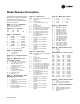
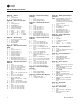
Model Number Description Following is a complete description of the blower coil model number. Each digit in the model number has a corresponding code that identifies specific unit options.
Model Number Description Digit 24 — Filters 0 A B = = = none 1” throwaway 2” pleated throwaway Digit 25 — Accessory Section 0 A B C D E F G H J K = = = = = = = = = = = none mixing box only angle filter box angle filter/mixing box top access filter box bottom access filter A&D L = C&H A&E M = D&H steam coil N = E & H A&H P = A, D, & H B&H R = A, E, & H Digit 26 — Control Type 0 1 2 3 4 = = = = = no controls (4 x 4 junction box) control interface Tracer™ ZN010 Tracer ZN510 Tracer ZN520 Digit 27 — Un
General Information Blower Coil General Information Blower coil units are draw-thru air handlers for cooling load conditions of 400–3000 cfm. Units are available in either horizontal (model BCHC) or vertical (model BCVC) configurations. Horizontal units are typically ceiling suspended via threaded rods. Knockouts are provided in all four corners to pass the rods through the unit. Horizontal units can also be floor mounted. Vertical units are typically floor mounted.
General Information a control valve and stop (ball) valves. The deluxe package consists of a control valve, a stop (ball) valve, a circuit setter, and strainer. Belt-drive motors range from 1/3 to 3 horsepower in a wide range of voltages. All motors have internal thermal and current overloads, permanently sealed ball bearings, and a resilient cradle mount to reduce noise and vibration transmission.
Pre-Installation Receiving and Handling Blower coil units are packaged for easy handling and storage on the job site. Upon delivery, inspect all components for possible shipping damage. See the “Receiving Checklist” section (below) for detailed instructions. Trane recommends leaving units and accessories in their shipping packages/ skids for protection and handling ease until installation.
Pre-Installation Installation Preparation Before installing the unit, perform the following procedures to ensure proper unit operation. 1. Verify the floor or foundation is level. Shim or repair as necessary. To ensure proper unit operation, install the unit level (zero tolerance) in both horizontal axes. Failure to level the unit properly can result in condensate management problems, such as standing water inside the unit.
Pre-Installation Figure 2. Top view of blower coil unit showing recommended service and code clearances 3 3 Rigging and Handling Before preparing the unit for lifting, estimate the approximate center of gravity for lifting safety. Because of placement of internal components, the unit weight may be unevenly distributed, with more weight in the coil area. Approximate unit weights are given in “Dimensions and Weights,” p. 15. Also, you may reference the unit weight on the unit nameplate.
Pre-Installation 1. Consider the unit weight. Reference the unit weight on the unit nameplate or in “Dimensions and Weights,” p. 15. 2. Allow sufficient space for the recommended clearances, access panel removal, and maintenance access. Refer to Figure 2, p. 13. 3. The installer must provide threaded suspension rods for ceiling mounted units. All units must be installed level. 4. Coil piping and condensate drain requirements must be considered. Allow room for proper ductwork and electrical connections.
Dimensions and Weights Horizontal Blower Coil *NOTE: ON UNITS WITHOUT A BOTTOM FILTER ACCESS SECTION top view M M M P P Q 1.5 JJ front view Table 2. Unit size Horizontal blower coil dimensions (in.) and weights (lb) H W A B C Basic unit weight D E F K M P Q 12 14.00 24.00 39.75 12.09 18.00 10.56 7.09 0.55 3.00 11.42 13.42 9.42 11.42 4.20 8.46 9.00 5.75 70.40 18 14.00 28.00 39.75 12.09 22.00 10.56 7.09 0.55 3.00 11.42 13.42 9.42 11.42 4.20 10.46 9.00 5.75 76.
Dimensions and Weights Vertical Blower Coil *NOTE; ON UNITS WITHOUT A TOP FILTER ACCESS SECTION vertical counter swirl configuration top view vertical preswirl configuration M M 6.00 P Q J front view Table 3. Unit size Vertical blower coil dimensions (in.) and weights (lb) H W L A B C D E F G G J J (RH) (LH) (RH) (LH) 24 63.50 28.00 44.00 16.09 22.00 13.56 12.56 1.30 3.00 11.42 13.42 9.42 K M N P Q R Basic unit weight 11.42 6.20 5.50 18.00 9.00 5.50 28.00 150.30 5.50 18.
Dimensions and Weights Angle Filter and Mixing Box combination angle filter & mixing box mixing box angle filter box Table 4. Angle filter and mixing box dimensions (in.) and weights (lb) Unit size H L W A B Weight 12 14.12 22.00 24.11 7.06 15.56 36.0 16 14.12 22.00 28.11 7.06 19.56 41.0 24 18.12 19.50 28.11 7.06 19.56 43.0 36 18.12 24.50 40.11 7.06 31.56 56.0 54 22.12 23.50 40.11 12.81 31.56 72.0 72 22.00 23.50 48.00 12.81 32.56 72.5 90 27.90 27.
Dimensions and Weights Bottom or Top Access Filter Box 7.17 .97 FILTER AIR FLOW FILTER AIR FLOW top view FILTER ACCESS PANEL NOTES; 1. DIMENSIONS ARE IN INCHES. 2. ROTATE 180° FOR TOP ACCESS. 3. SECTIONS SHIPS ATTACHED TO THE UNIT. right side view Table 5. Bottom or top access filter box dimensions (in.) and weights (lb) Unit size H W A B C D Weight 12 14.00 24.00 9.98 2.01 18.23 2.88 15 18 14.00 28.00 9.98 2.01 21.98 3.01 17 24 18.00 28.00 14.23 1.89 23.23 2.
Dimensions and Weights Electric Heat & 90 top view D front view right side view & 90 & 90 ARE HINGED ELECTRIC HEAT MAY NEED FIELD-SUPPLIED EXTERNALLY-WRAPPED INSULATION IF THE UNIT IS INSTALLED IN AN UNCONDITIONED SPACE OR IF SWEATING IS AN ISSUE. Table 6. Electric heat dimensions (in.) and weights (lb) Unit size H W A B C D E Weight 12 14.06 18 14.06 17.88 8.13 6.79 10.50 7.75 0.03 10.0 19.88 10.13 8.79 10.50 7.75 0.03 24 10.8 18.06 21.25 7.63 6.29 13.50 12.63 0.
Dimensions and Weights Steam Coil ACCESS PANEL HEATING COIL 0.97 NOTES: 1. FILTER ACCESS & ACCESS PANEL LOCATED ON BOTH SIDES. 2. WEIGHT INCLUDES CABINET WITH AVERAGE FILTER, BUT DOES NOT INCLUDE CIOL WEIGHT. SEE GENERAL DATA SECTION FOR COIL WEIGHTS. AIRFLOW C H A 0.97 21.00 C B W FILTER ACCESS Table 7. Steam coil box dimensions (in.) and weights (lb) Coil Connections, NPT Unit size H W A B C Weight Supply Return 12 14.00 24.00 12.06 18.04 2.98 34 1 3/4 18 14.00 28.
Dimensions and Weights Coil Connections Table 8. Hydronic coil connection sizes, OD (in.) Standard capacity High capacity Unit size 1-row 4-row 6-row 2-row 4-row 6-row 12 5/8 - - 5/8 7/8 7/8 18 5/8 - - 5/8 7/8 7/8 24 5/8 - - 7/8 1-1/8 1-1/8 36 7/8 - - 7/8 1-1/8 1-1/8 54 1-1/8 1-3/8 1-3/8 1-1/8 1-1/8 1-1/8 72 1-1/8 1-3/8 1-3/8 1-1/8 1-1/8 1-1/8 90 1-1/8 1-5/8 1-5/8 1-1/8 1-1/8 1-1/8 Table 9. DX coil connection sizes, OD (in.
Dimensions and Weights Piping Packages Basic Piping Two-way, 1/2” and 1” valve basic piping package B A B A Two-way, 1-1/4” valve basic piping package A B AB E B A Three-way, 1/2” and 1” valve basic piping package F A B AB E A 22 B BCXC-SVX01B-EN
Dimensions and Weights Deluxe Piping Two-way, 1/2” and 1” valve deluxe piping package D B A C Two-way 1-1/4” valve deluxe piping package D A B AB E C BCXC-SVX01B-EN 23
Dimensions and Weights Three-way, 1/2” and 1” valve deluxe piping package F A B AB E C D Table 11. Piping package dimensions (in.) Piping package 2-way 3-way 24 Nominal tube size Actual size A B C D E F 1/2 5/8 12.025 2.650 12.625 5.650 N/A N/A 1 1-1/8 13.295 4.260 13.220 9.288 3.020 N/A 6.351 1/2 5/8 12.088 2.097 12.688 4.497 6.351 3/4 7/8 15.623 1.750 15.313 6.290 6.701 6.701 1 1-1/8 13.370 3.690 13.210 9.060 9.813 9.813 1-1/4 1-3/8 16.885 3.
Installation Controls Installing Wall Mounted Controls Wall mounted zone sensors ship taped to the control box. Refer to Figure 3 for zone sensor dimensions. Position the controller on an inside wall three to five feet above the floor and at least 18 inches from the nearest outside wall. Installing the controller at a lower height may give the advantage of monitoring the temperature closer to the zone, but it also exposes the controller to airflow obstructions.
Installation Controls b. Pull the control wires through the cutout. Attach the module to the wall using the screws provided. 5. Strip the insulation on the interconnection wires back 0.25 inch and connect to TB1. Screw down the terminal blocks. 6. Replace the zone sensor cover and adjustment knob. If installing a Tracer™ ZN510 or ZN520 zone sensor, see “Tracer Summit Communication Wiring,” p. 27 for more information.
Installation Controls Peer-to-peer communication across controllers is possible even when a building automation system is not present.You do not need to observe polarity for Comm5 communication links. The controller provides six 0.
Installation Electrical Unit Wiring Diagrams Specific unit wiring diagrams are provided on the inside of the control panel door. Typical unit wiring diagrams are in “Wiring Diagrams,” p. 81. Use these diagrams for connections or trouble analysis. WARNING Grounding Required! Follow proper local and state electrical codes for requirements on grounding. Failure to follow code could result in death or serious injury. Supply Power Wiring Wiring must conform to NEC and all applicable code requirements.
Installation Electrical 3. If the unit has a electric heat: power and ground connections are inside the electric heat control box, connected to a non-fused disconnect switch or terminal block. Electrical Grounding Restrictions WARNING Hazardous Voltage! Disconnect all electric power, including remote disconnects before servicing. Follow proper lockout/tagout procedures to ensure the power can not be inadvertently energized.
Installation Electrical See Table 13 for electric heat kW and Table 14, p. 31 for motor FLAs. Select a standard fuse size or HACR type circuit breaker equal to the MCA. Use the next larger standard size if the MCA does not equal a standard size. Standard fuse sizes are: 15, 20, 25, 30, 35, 40, 45, 50, 60 amps Useful Formulas kW = (cfm x ΔT)/3145 ΔT = (kW x 1000)/voltage Single phase amps = (kW x 1000)/voltage Three phase amps = (kW x 1000)/(voltage x 1.73) Electric heat MBh = (Heater kW) (3.413) Table 13.
Installation Electrical Table 14. Motor electrical data Voltage 115/60/1 Voltage range rpm Rated hp lb FLA 104–126 1750 1/3 18 5.8 LRA 22.8 1/2 21 7.2 30.4 3/4 29 12.0 58.4 1.0 29 12.8 58.4 Two-speed 115/60/1 208–230/60/1 277/60/1 208/60/3 230/60/3 460/60/3 575/60/3 104–126 187–253 249–305 187–229 207–253 414–506 518–632 1750/1160 1750 1750 1750 1750 1750 1750 3/4 40 8.9/6.1 42.0 1.0 41 11.5/8.1 58.2 1/3 18 3.1 11.4 1/2 21 3.6 15.2 3/4 29 6.
Installation Electrical Table 14. Motor electrical data (continued) Voltage 220/50/1 240/50/1 Voltage range rpm Rated hp lb FLA LRA 198–242 1450 1/3 20.5 3.0 15.6 1/2 25 3.6 20.5 3/4 29 5.2 25.6 1.0 38 9.3 52.2 1/3 20.5 3.3 17.1 1/2 25 4.0 22.7 3/4 29 5.5 39.1 1.0 38 10.6 57.8 216–264 190/50/3 171–209 380/50/3 342–418 415/50/3 374–456 1450 1450 1450 1/3 22 1.1 5.6 1/2 26 1.4 7.8 3/4 28 1.7 9.8 1.0 29 2.1 14.6 1.5 34 2.8 18.7 2.
Installation Mechanical WARNING Hazardous Voltage! Disconnect all electric power, including remote disconnects before servicing. Follow proper lockout/tagout procedures to ensure the power can not be inadvertently energized. Failure to disconnect power before servicing could result in death or serious injury. Installing the Unit Follow the procedures below to install the blower coil unit.
Installation Mechanical 4. Guide the threaded rod through the unit from the top, careful not to damage insulation or wiring. See Figure 5. Insert the threaded rod at an angle to help prevent internal unit damage. Figure 5. When inserting the threaded rod though the unit knockouts, angle it through the top, careful not to damage unit coil or insulation. 5. Put a nut and large flat washer or steel plate on the bottom of the threaded rod. See Figure 6. Figure 6.
Installation Mechanical required. The unit is shipped in two pieces, and can be arranged in either a pre-swirl or counterswirl inlet configuration (see Figure 7). Figure 7. Typical vertical unit installation Heating Coil Option Note: The hydronic heating coil option is factory installed in either the reheat or preheat position. Coils can be rotated for either right or left-hand connections.
Installation Mechanical • interconnecting linkage, LH or RH attachment Materials needed: • grooved and extendible drive rods, 1/2-inch O.D. grooved • screws The mixing box option ships separately for field installation. It has two low-leak, opposed blade dampers and all necessary interconnecting linkage components for left or right hand attachment onto 1/2-inch O.D. grooved, extendible drive rods. Also, mounting legs are provided for floor mounting on a vertical unit.
Installation Mechanical Plug or trap the auxiliary connection to prevent air from being drawn in and causing carryover (see Figure 8). Figure 8. Recommended drain trap installation for draw-through units ‘ H = 1” of length for each 1” of negative pressure + 1”additional J = 1/2 of H L = H + J + pipe diameter + insulation All drain lines downstream of the trap must flow continuously downhill. If segments of the line are routed uphill, this can cause the drain line to become pressurized.
Installation Piping Water Coil Connections Water coils have sweat connections. Reference coil connection dimensions in “Dimensions and Weights,” p. 15. Proper installation and piping is necessary to ensure satisfactory coil operation and prevent operational damage. Water inlet and outlet connections extend through the coil section side panel (see Figure 9). Follow standard piping practices when piping to the coil. Figure 9.
Installation Piping diameter must be as small as possible, while still providing at least 5°F [2.7°C] of subcooling at the expansion valve throughout the operating envelope. Routing. Install the liquid line with a slight slope in the direction of flow so that it can be routed with the suction line. Minimize tube bends and reducers because these items tend to increase pressure drop and reduce subcooling at the expansion valve. Insulation.
Installation Piping Routing. To prevent residual or condensed refrigerant from “free-flowing” toward the compressor, install the suction line so it slopes slightly—1 inch per 10 feet of run [1 cm per 3 m]— toward the evaporator. Avoid putting refrigerant lines underground. Refrigerant condensation, installation debris inside the line, service access, and abrasion/corrosion can quickly impair system reliability. Insulation.
Installation Piping Steam Piping Proper installation, piping and trapping is necessary to insure satisfactory heating coil operation and prevent operational damage under service conditions. These installation recommendations and piping diagram (see Figure 11, p. 42) must be followed to assure satisfactory, trouble-free operation. General 1. Support all piping independently of coils. 2.
Installation Piping 6. Do not modulate steam or use on-off supply control on systems with overhead or pressurized returns unless condensate is drained by gravity to receiver (vented to atmosphere) and returned to main by condensate pump. 7. At startup with dampers, slowly turn steam on full for at least 10 minutes before opening fresh air intake. 8. Pitch all supply and return steam piping down a minimum of one inch per 10 feet in direction of flow. 9. Do not drain steam mains or take-offs through coils.
Controls Interface Control Options Blower coil air handlers are available without controls or with one of four different control options: • Control interface • Tracer™ ZN010 • Tracer ZN510 • Tracer ZN520 Units without controls have a junction box mounted on the drive side for motor power wire terminations. The controller is easily accessible in the control box for service. Control option descriptions follow below.
Controls Interface • Zone setpoint • Current zone temperature • Fan mode selection (off-auto-high-low) For optimal system performance, blower coil units can operate as part of an Integrated Comfort™ System (ICS) building automation system controlled by Tracer Summit®. The controller is linked directly to the Summit control panel via a twisted pair communication wire, requiring no additional interface device (i.e., a command unit). The Trane ICS system can monitor or override ZN520 control points.
Controls Interface Table 16. Tracer controller function summary Tracer™ Controller ZN010 ZN510 ZN520 Entering water temp.
Pre-Start Pre-Start Checklist Complete this checklist after installing the unit to verify all recommended installation procedures are complete before unit startup. This does not replace the detailed instructions in the appropriate sections of this manual. Disconnect electrical power before performing this checklist. Always read the entire section carefully to become familiar with the procedures. WARNING Hazardous Voltage! Disconnect all electric power, including remote disconnects before servicing.
Pre-Start Component Overview Verify the fan and motor shafts are parallel. Verify the fan and motor sheaves are aligned. Check the belt tension for proper adjustment. Adjust the belt tension if it is floppy or squeals continually. Ensure the fan rotates freely in the correct direction. Tighten locking screws, bearing set screws and sheaves. Ensure bearing locking collars do not wobble when rotated and correct torque settings. Refer to Table 31, p. 64 for recommended torques.
Start-Up Sequence of Operation Tracer ZN Controller Sequence of Operation Controller Start-Up Refer to Trane publication CNT-SVX04A-EN, Installation, Operation, and Programming Guide, to operate the Tracer™ ZN controller with Trane Integrated Comfort™ System (ICS). The factory preprograms the Tracer ZN controller with default values to control the temperature and unit airflow. Use Tracer Summit® building automation system or Rover™ software to change the default values.
Start-Up 3. Default operation of the controller (occupied mode) 4. Communicated request, usually provided by the building automation system (BAS) or peer device (available on Tracer™ ZN510 and ZN520 only) Table 18. Occupancy sensor state Sensor type Sensor position Unit occupancy mode Normally open Open Occupied Normally open Closed Unoccupied Normally closed Open Unoccupied Normally closed Closed Occupied A communicated request will control the controller’s occupancy.
Start-Up enabled (Tracer™ ZN520 only) and possible, it is the primary cooling capacity. If hydronic heating is possible, it will be the primary heating capacity. Occupied Standby Mode (Tracer ZN510 or ZN520 only) The controller can be placed into the occupied standby mode when a communicated occupancy request is combined with the local (hardwired) occupancy binary input signal.
Start-Up Note: Unit diagnostics can affect fan operation, causing occupied and occupied standby fan operation to be defined as abnormal. Refer to “Troubleshooting,” p. 72 for more information about abnormal fan operation. Economizer Cooling (Tracer ZN520 Only) The economizer provides cooling whenever the outdoor temperature is below the economizer enable setpoint and there is a need for cooling.
Start-Up heating capacity of the unit (0–100%). The outputs are controlled based on the unit configuration and the required heating capacity. Fan Mode Operation WARNING Rotating Components! Disconnect all electric power, including remote disconnects before servicing. Follow proper lockout/tagout procedures to ensure the power can not be inadvertently energized. Failure to disconnect power before servicing could result in death or serious injury.
Start-Up Additional flexibility built into the controller allows you to enable or disable the local fan switch input. The fan mode request can be hardwired to any of the Tracer™ ZN controllers or communicated to the Tracer ZN510 or ZN520 controller. When both inputs are present, the communicated request has priority over the hardwired input. See Table 19, p. 52. Fan Speed Switch Off. Fan is turned off, two-position damper option spring-returns closed. High or Low.
Start-Up Fan Cycling Operation Tracer™ ZN520 does not support fan cycling in occupied mode. The fan cycles between high speed and off in the unoccupied mode only. The controller’s cascade control algorithm requires continuous fan operation in the occupied mode. Fan Off Delay When a heating output is controlled off, the Tracer™ ZN controller automatically holds the fan on for an additional 30 seconds.
Start-Up Table 23. Local fan switch enabled Communicated Fan switch (local) Fan operation fan speed input Off Ignored Off Low Ignored Low High Ignored High Auto Off Off Low Low High High Auto Auto (configured default, determined by heat/cool mode) Table 24.
Start-Up flows normally and frequently through the coil, the controller does not invoke the sampling function because the EWT is satisfactory. Table 25.
Start-Up temperature rises 5°F above the economizer enable point, the controller disables economizing and moves the fresh air damper back to its predetermined minimum position based on the current occupancy mode or communicated minimum damper position. Table 26.
Start-Up temperature diagnostic when detecting low temperature. In addition, Tracer ZN controls unit devices as listed below: Fan: Off Valves: Open Electric heat: Off Damper: Closed Note: See the “Diagnostics” section for more information. BIP2: Condensate Overflow Detection Option The factory hard wires the condensate overflow sensor to binary input #2 (BIP2) on the Tracer™ ZN controller. The sensor defaults normally closed (N.C.
Start-Up Analog Inputs See Table 28 for a complete description of analog inputs. Table 28. Analog inputs Analog input Terminal Function Range ZN010 ZN510 ZN520 Zone TB3-1 Space temperature input Ground TB3-2 Analog ground 5° to 122°F (-15° to 50°C) • • • N/A • • Set TB3-3 • Setpoint input 40° to 115°F (4.4° to 46.
Start-Up Table 29. Binary output configuration Binary output pin connection Configuration ZN010 ZN510 ZN520 J1-1 Fan high • • • J1-2 N/A • • J1-3 Fan low J1-4 • • (Key) • Fan low • • J1-5 Main valve – open, or 2 pos. valve(a) • • J1-6 Aux. valve/elec. ht. • • • • Aux. valve – close(a) • • J1-7 2-pos. damper J1-9 Heat valve – open, or 2 pos. valve, or first stage elec. ht.(a) • J1-10 Heat valve – close or sec. stage elec. ht.
Start-Up temperature value exists, the controller ignores the hardwired space temperature input and uses the communicated value. Local Setpoint The zone sensor may be equipped with a thumbwheel for setpoint adjustment. Fan Mode Switch The zone sensor may be equipped with a fan mode switch. The fan mode switch offers selections of off, low, high, or auto.
Start-Up When the fan switch is in the off position, the controller does not control any unit capacity. The unit remains powered and all outputs drive to the closed position. Upon a loss of signal on the fan speed input, the controller reports a diagnostic and reverts to using the default fan speed. On/Cancel Buttons Momentarily pressing the on button during unoccupied mode places the controller in occupied bypass mode for 120 minutes.
Maintenance Maintenance Procedures Perform the following maintenance procedures to ensure proper unit operation. Air Filters Always install filters with directional arrows pointing toward the fan. Fan Bearings Fan bearings are permanently sealed and lubricated and do not require additional lubrication. Fan Motors Inspect fan motors periodically for excessive vibration or temperature. Operating conditions will vary the frequency of inspection and lubrication.
Maintenance sheaves and pull tight. Adjust sheaves and tighten the sheave set screws to the correct torques recommended in Table 31. Figure 15. Clearance recommendation to prevent fan frame and belt interface Figure 16. Correct sheave alignment Table 31. Recommended torques for tightening sheaves and bearing thrust collar Torque (in.-lb) Ft-lb N-m Sheave setscrew 144 12 16.3 Bearing thrust collar 66 5.5 7.5 Fan wheel screw 144 12 16.
Maintenance NOTICE Belt tension! Do not over-tension belts. Excessive belt tension will reduce fan and motor bearing life, accelerate belt wear, and could result in shaft failure. Table 32. BCHC/BCVC fan, filter, and mixing box general data Unit size 12 18 24 36 54 72 90 Nominal cfm 400 600 800 1200 1800 2400 3000 Minimum cfm 250 375 500 750 1125 1500 1875 Maximum cfm 500 675 1000 1600 2400 3000 4000 9.5 x 4.5 9.5 x 4.5 9.5 x 9.5 9.5 x 9.5 12.6 x 9.5 12.6 x 9.5 12.
Maintenance Table 34. BCHC/BCVC coil general data Unit size 12 18 24 36 54 72 90 Nominal cfm 400 600 800 1200 1800 2400 3000 Area - ft2 0.89 1.11 1.67 2.67 4.00 5.00 6.67 Width - in. (a),(b) 8 8 12 12 18 18 24 Length - in. (c) 16 20 20 32 32 40 40 Velocity - ft/min. 450 540 480 450 450 480 450 0.89 1.11 1.67 2.67 3.89 4.86 6.25 Hydronic & DX coil data Hydronic coil data • High-capacity Area - ft2 (a),(d) 8 8 12 12 17.5 17.5 22.5 Length - in.
Maintenance Table 34. BCHC/BCVC coil general data (continued) Unit size 12 18 24 36 54 72 90 Nominal cfm 400 600 800 1200 1800 2400 3000 Minimum gpm (e) N/A N/A N/A N/A 8.8 8.8 11.7 (f) 62.6 6-row coil • Standard capacity N/A N/A N/A N/A 47.0 47.0 Dry coil weight - lb (g) N/A N/A N/A N/A 52.4 63.1 82.7 Wet coil weight - lb (g) N/A N/A N/A N/A 68.1 82.0 108.7 Internal volume - in3 (g) N/A N/A N/A N/A 434.8 523.4 720.0 Minimum gpm (e) 2.0 2.0 2.
Maintenance Table 35.
Maintenance Coil Maintenance Keep coils clean to maintain maximum performance. For operation at its highest efficiency, clean the coil often during periods of high demand or when dirty conditions prevail. Clean the coil a minimum of once per year to prevent dirt buildup in the coil fins, where it may not be visible. Remove large debris from the coils and straighten fins before cleaning. Remove filters before cleaning. Rinse coils thoroughly after cleaning.
Maintenance Winterizing the Coil Make provisions to drain coils that are not in use, especially when subjected to freezing temperatures. To drain the coil, first blow out the coil with compressed air. Next, fill and drain the tubes with fullstrength ethylene glycol several times. Then drain the coil as completely as possible. NOTICE Potential coil-freeze condition! Make provisions to drain the coil when not in use to prevent coil freeze-up.
Maintenance 2. Visually inspect the entire unit casing for chips or corrosion. Remove rust or corrosion and repaint surfaces. 3. Clean fan wheels and fan shaft. Remove any rust from the fan shaft with an emery cloth and recoat with L.P.S. 3 or equivalent. 4. Inspect the drainpan for sludge or other foreign material. Clear the drain openings and drain line to ensure adequate flow. 5. Rotate the fan wheel and check for obstructions in the fan housing. The wheel should not rub on the fan housing or cutoff.
Diagnostics Troubleshooting LED Activity Red Service LED The red LED normally indicates if the unit controller is operating properly or not. Refer to Table 36. Table 36. Red service LED activity‘ LED activity Description Off continuously after power is applied to the controller. Normal operation On continuously, even when power is first applied to the Someone is pressing the Service button or the controller controller. has failed. LED flashes about once every second. Uninstall (normal controller mode).
Diagnostics Service LED section. Use Rover™ service tool to restore the unit to normal operation. Refer to the Rover product literature for more information. Manual Output Test The purpose of the manual output test sequence is to verify output and end device operation. Use the manual output test to: • Verify output wiring and operation without using Rover™, service tool. • Force the water valve to open and balance the hydronic system. Note: The manual output test is not an automatic cycle.
Diagnostics Table 39. Tracer ZN010 and ZN510 test sequence for 1-heat/1-cool configurations Cool output(a) Fan Steps J1-1, J1-3 1. Off Off J1Off Heat output Damper J1- J1- Off Closed 2. Fan high High Off Off Closed 3. Exhaust fan (b) Off Off Closed 4. Fan Low Off Off Closed 5. Cool High On Off Closed 6. Heat High Off On Closed 7. Two-position damper(c) High Off Off Open 8.
Diagnostics • • • • • • • • • • • • • • • • • • Low temperature detection Condensate overflow Low air flow - fan status Discharge air temp limit Space temperature failure1 Entering water temp failure1 Discharge air temp failure Outdoor air temp failure1 Local setpoint failure1 Local fan mode failure1 CO2 sensor failure1 Generic AIP failure1 Humidity input failure1 Defrosting compressor lockout1 Maintenance required Invalid Unit Configuration Generic temperature failure Discharge air low limit Resetting D
Diagnostics Manual Output Test You can use the Test button on the controller either during installation to verify proper end device operation or during troubleshooting. When you press the Test button, the controller exercises all outputs in a predefined sequence. The first and last outputs of the sequence reset the controller diagnostics. See p. 73 for more information about the manual output test.
Diagnostics Table 41.
Diagnostics Common Diagnostics Table 43. Fan outputs do not energize Probably cause Explanation Random start observed After power-up, the controller always observes a random start that varies between 0 and 30 seconds. The controller remains off until the random start time expires. Power-up control wait When power-up control wait is enabled (non-zero time), the controller remains off until one of two conditions occurs: 1.
Diagnostics Table 45. Valves stay open Probable cause Explanation Normal operation The controller opens and closes the valves to meet the unit capacity requirements. Valve override The controller can communicate a valve override request to affect the valve operation. Manual output test The controller includes a manual output test sequence that verifies analog and binary output operation and the associated wiring. However, based on the current step in the test sequence, the valves may be open.
Diagnostics Table 48. Fresh air damper stays open Probable cause Explanation Normal operation The controller opens and closes the fresh air damper based on the controller’s occupancy mode and fan status. Normally, the fresh air damper is open during occupied mode when the fan is running and closed during unoccupied mode. Manual output test The controller includes a manual output test sequence that verifies analog and binary output operation and associated wiring.
Wiring Diagrams Two-Pipe BCXC with Tracer ZN510 • • • • • • 208 volt/3 phase 2-position damper single stage electric heat 2-position valve condensate overflow wall-mounted zone sensor WARNING Hazardous Voltage! Disconnect all electric power, including remote disconnects before servicing. Follow proper lockout/tagout procedures to ensure the power can not be inadvertently energized. Failure to disconnect power before servicing could result in death or serious injury.
Wiring Diagrams Four-Pipe BCXC with Tracer ZN510 • • • • • • 208 volt/3 phase 2-position valves 2-position damper condensate overflow low limit protection wall-mounted zone sensor WARNING Hazardous Voltage! Disconnect all electric power, including remote disconnects before servicing. Follow proper lockout/tagout procedures to ensure the power can not be inadvertently energized. Failure to disconnect power before servicing could result in death or serious injury.
Wiring Diagrams Four-Pipe BCXC with Tracer ZN510 • • • • • 115 volt/1 phase 2-position valves 2-position damper 2-speed motor condensate overflow WARNING Hazardous Voltage! Disconnect all electric power, including remote disconnects before servicing. Follow proper lockout/tagout procedures to ensure the power can not be inadvertently energized. Failure to disconnect power before servicing could result in death or serious injury.
Wiring Diagrams Two-Pipe BCXC with Tracer ZN520 • • • • • • • 460 volt/3 phase 2-position valve economizer damper 2-stage electric heat fan status switch condensate overflow wall-mounted zone sensor WARNING Hazardous Voltage! Disconnect all electric power, including remote disconnects before servicing. Follow proper lockout/tagout procedures to ensure the power can not be inadvertently energized. Failure to disconnect power before servicing could result in death or serious injury.
Wiring Diagrams Four-Pipe BCXC with Tracer ZN520 • • • • 460 volt/3 phase 2-position valves condensate overflow fan status switch WARNING Hazardous Voltage! Disconnect all electric power, including remote disconnects before servicing. Follow proper lockout/tagout procedures to ensure the power can not be inadvertently energized. Failure to disconnect power before servicing could result in death or serious injury.
Wiring Diagrams Four-Pipe BCXC with Tracer ZN520 • • • • • 460 volt/3 phase economizer damper condensate overflow fan status switch wall-mounted zone sensor WARNING Hazardous Voltage! Disconnect all electric power, including remote disconnects before servicing. Follow proper lockout/tagout procedures to ensure the power can not be inadvertently energized. Failure to disconnect power before servicing could result in death or serious injury.
Wiring Diagrams Four-Pipe BCXC with Tracer ZN520 • • • • • • 460 volt/3 phase 3-wire floating point valves economizer damper condensate overflow fan status switch wall-mounted zone sensor WARNING Hazardous Voltage! Disconnect all electric power, including remote disconnects before servicing. Follow proper lockout/tagout procedures to ensure the power can not be inadvertently energized. Failure to disconnect power before servicing could result in death or serious injury.
Wiring Diagrams Four-Pipe BCXC with Control Interface • • • • • • 208 volt/3 phase • 3-wire floating point valves • 2-position damper • low limit protection • condensate overflow WARNING Hazardous Voltage! Disconnect all electric power, including remote disconnects before servicing. Follow proper lockout/tagout procedures to ensure the power can not be inadvertently energized. Failure to disconnect power before servicing could result in death or serious injury.
Wiring Diagrams Four-Pipe BCXC with Control Interface • • • • • 115 volt/1 phase 2-position damper 2-speed motor condensate overflow low limit protection WARNING Hazardous Voltage! Disconnect all electric power, including remote disconnects before servicing. Follow proper lockout/tagout procedures to ensure the power can not be inadvertently energized. Failure to disconnect power before servicing could result in death or serious injury.
Wiring Diagrams BCXC with DX Coil and Tracer ZN520 • • • • 1 2 3 NOTES: 1 UNLESS OTHERWISE NOTED, ALL SWITCHES ARE SHOWN AT 25° C (77° F), AT ATMOSPHERIC PRESSURE, AT 50% RELATIVE HUMIDITY, WITH ALL UTILITIES TURNED OFF, AND AFTER A NORMAL SHUTDOWN HAS OCCURED. DEVICE PREFIX LOCATION CODE LOCATION MAIN CONTROL PANEL SUPPLY FAN AND COIL SECTION 277/60/1 N L1 AREA 1 2 3 4 5 6 7 2 DASHED LINES INDICATE RECOMMENDED FIELD WIRING BY OTHERS.
Wiring Diagrams BCXC with DX Coil, Hydronic Heating, and Tracer ZN520 • • • • 2 DASHED LINES INDICATE RECOMMENDED FIELD WIRING BY OTHERS. DASHED LINE ENCLOSURES AND/OR DASHED DEVICE OUTLINES INDICATE COMPONENTS PROVIDED BY THE FIELD. SOLID LINES INDICATE WIRING BY TRANE CO. 4 NUMBERS ALONG THE RIGHT SIDE OF THE SCHEMATIC DESIGNATE THE LOCATION OF CONTACTS BY LINE NUMBER. 5 FIELD SUPPLIED CONTROL RELAYS, POWERED BY THIS UNIT, MUST BE PILOT DUTY RATED, 24VAC COIL, 6VA MAX.
www.trane.com For more information, contact your local Trane office or e-mail us at comfort@trane.com Literature Order Number BCXC-SVX01B-EN Date April 2008 Supersedes BCXC-SVX01A-EN September 2002 Trane has a policy of continuous product and product data improvement and reserves the right to change design and specifications without notice.