Installation, Operation, and Maintenance Variable Refrigerant Flow System Big Duct Indoor Unit Series Models: 4TVA0096B100NB, 4TVA0076B100NB SAFETY WARNING Only qualified personnel should install and service the equipment. The installation, starting up, and servicing of heating, ventilating, and air-conditioning equipment can be hazardous and requires specific knowledge and training. Improperly installed, adjusted or altered equipment by an unqualified person could result in death or serious injury.
Introduction Read this manual thoroughly before operating or servicing this unit. Warnings, Cautions, and Notices Safety advisories appear throughout this manual as required. Your personal safety and the proper operation of this machine depend upon the strict observance of these precautions. The three types of advisories are defined as follows: Indicates a potentially hazardous situation which, if not avoided, could result in death or serious injury.
Table of Contents Introduction . . . . . . . . . . . . . . . . . . . . . . . . . . . . . . . . . . . . . . . . . . . . . . . . . . . . . . . . . . . . 2 Warnings, Cautions, and Notices . . . . . . . . . . . . . . . . . . . . . . . . . . . . . . . . . . . . . 2 Important Environmental Concerns . . . . . . . . . . . . . . . . . . . . . . . . . . . . . . . 2 Important Responsible Refrigerant Practices . . . . . . . . . . . . . . . . . . . . . . . 2 Model Number Description . . . . . . . . . . . . . . . . . .
Operating Mode for Heat Pump Systems . . . . . . . . . . . . . . . . . . . . . . . . . . . . . External Static Pressure Setting . . . . . . . . . . . . . . . . . . . . . . . . . . . . . . . . . . . . . Cleaning the Exterior . . . . . . . . . . . . . . . . . . . . . . . . . . . . . . . . . . . . . . . . . . . . . . Periodic Maintenance Checks . . . . . . . . . . . . . . . . . . . . . . . . . . . . . . . . . . . . . . . 33 33 34 34 Troubleshooting . . . . . . . . . . . . . . . . . . . . . . . . . . . . . .
Model Number Description 4 T V D 0 0 1 8 A 1 0 0 N A 1 2 3 4 5 6 7 8 9 10 11 12 13 14 Digit 1: Refrigerant 4 = R410A Digit 2: Brand name T = Trane Digit 3: System type V = Variable Refrigerant Flow Digit 4: Configuration Type (also see separate tab) B = mini 4-way cassette C = 4-way cassette D = MSP duct type (mid-pressure) E = 1-way cassette L = Slim duct type (low pressure) A = HSP duct type high pressure) X = Ceiling W = High-wall Digit 5: Reserved for future use 0 = Not
Preparing for Installation Preparing for Installation Accessories In addition to product literature, the following accessories are supplied with this unit. The type and quantity may differ, depending on the model.
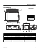
Preparing for Installation Unit Dimensions Unit: inch (mm) 7 36.0 (914) suspension pos. 41.0 (1040) 51.4 (1306) suspension position 46.8 (1188) air inlet duct flange 5.5 (140) x 8 = 44.1 (1120) A 5.5 (140) x 8 = 44.1 (1120) 46.8 (1188) air outlet duct flange 48.9 (1240) 6 3.9 (100) x 2 = 7.9 (200) B 3.7 (93) C 0.9 (22) D 1.1 (29) E 8.2 (209) F 9.3 (236) 26.0 (660) 15.2 (385) B D E F A 1.8.5 (470) 1.4 (35) OD 1.26 (32) C 25.5 (647) 23.6 (598) Suction side Discharge side No.
Preparing for Installation Service Clearances CAUTION Avoid Contact with Fan Motor Blower! Unit depth (D) + 1.97 (50) Install the unit at least 7.54 ft (2.2 m) from the floor to avoid the possibility of contact with the fan motor blower while cleaning the duct. Failure to follow this installation requirement could result in minor to moderate injury. Unit width (W) B = 19.7 (500) A = W + 3.94 (100) 0.78 (20) Unit 0.
Installation Installation Review “Installation Considerations” before proceeding with installation. Follow the procedures in these sections in the order given. Note: Install the Y-joint before installing the indoor unit. Mounting the Unit If the ceiling is already constructed, piping must be laid into position before placing the unit inside the ceiling. CAUTION Avoid equipment damage and personal injury! Ensure that the ceiling is strong enough to support the weight of the indoor unit.
Installation 8. Maintain proper spacing between the unit and the ceiling; refer to the following figure. 0.78 (20) Unit 0.78 (20) Ceiling 9. Adjust the level of the unit so that it tilts1° to the side of the unit that will be connected to the drain hose. A tilt of 1°is also recommended when a drain pump is installed. Drain hose port 1° Purging the Unit The unit is shipped from the factory with a holding charge of nitrogen. All of this gas must be purged from the unit.
Installation Installing Refrigerant Piping Connect field-supplied piping using flared connections (not supplied) or by brazing. The large unit port is for gas refrigerant; the small one is for liquid refrigerant. Cut or extend field-supplied piping as needed. Use the following procedures. NOTICE System Failure! If brazing is used for pipe connections, a nitrogen purge is required to prevent the formation of copper oxides inside the piping. Failure to follow this procedure could damage the system.
Installation Conventional flare tool R-410A clutch type 0–0.020 in. Clutch type Wing nut type 0.04–0.06 in. 0.06–0.08 in. 3. Attach the yoke to the flaring bar, centering the conical part over the end of the pipe that is extending above the flaring bar. 4. Tighten the yoke securely to flare the end of the pipe. Yoke Flaring bar Copper pipe Flare nut 5. Remove the pipe. The end of the pipe that you flared should look like the end of a trumpet.
Installation Leak Testing Pipe Connections WARNING Confined Space Hazards! Do not work in confined spaces where refrigerant or other hazardous, toxic or flammable gas may be leaking. Refrigerant or other gases could displace available oxygen to breathe, causing possible asphyxiation or other serious health risks. Some gases may be flammable and or explosive. If a leak in such spaces is detected, evacuate the area immediately and contact the proper rescue or response authority.
Installation Installing the Drain System 1. Push the supplied drain hose as far as possible over the drain hose port. • Do not apply excessive force to the piping on the unit side when connecting the drain hose. • Drain hose port locations differ depending on the unit type. Drain hose Drain hose port Drain hose port 2. Wrap the insulation (supplied) around the drain hose and clamp the connection as tightly as possible until you can see at least 8 holes. Clamp Insulation 3.
Installation 4. Refer to appropriate figure for installing the drain pipe with out without a drain pump. Drain pipe installation with drain pump Air vent Unit: in. (mm) 11.8 (300) 7.87 (200) 39.4–59 (1000–1500) Hanger 0.79 (20) Flexible hose Note: Install a U-trap at the end of the drain pipe to prevent odors. Ceiling Drain pipe installation without drain pump 39.4–59 (1000–1500) Flexible hose Hanger H2 (50) Unit: in.
Installation Centralized Drainage If the installation requires more than three indoor units, install the main air vent at the front of the indoor unit that is farthest from the main drain. It may be necessary to install individual air vents to prevent water flowing back to each indoor unit. For installations without a drain pump, install U-traps at the end of the drain pipe for each unit.See figures below. Drain pipe installation with drain pump 39–59 in. (1–1.
Installation Testing the Drainage After completing the installation, test the drainage to make sure there are no leaks: 1. Operate the unit in cool mode. 2. Remove drain pump cover. 3. Squirt water into the drain pan (see figure). 4. Confirm that the water flows out through the drain hose and that no leakage occurs at any of the connections. 5. Reassemble the drain pump cover.
Insulation Insulation After determining that there are no leaks in the refrigerant pipes or drainage hose, insulate them as described in these sections. Refrigerant Pipes 1. Use the table below to select the insulation type for each pipe size. Insulation Type Pipe size (in. [mm]) Pipe Liquid pipe Gas pipe(b) High humidity conditions(a) (86°F [30°C], over 85%) Standard conditions (86°F [30°C], 85%) EPDM or NBR 1/4 (6.35) – 3/8 (9.52) 3/8 (9) 3/8 (9) 1/2 (12.70) – 2 (50.
Wiring the Unit Wiring the Unit Observe the following precautions when making electrical connections. WARNING Hazardous Voltage! Disconnect all electric power, including remote disconnects before servicing. Follow proper lockout/tagout procedures to ensure the power can not be inadvertently energized. Failure to disconnect power before servicing could result in death or serious injury. NOTICE Use Copper Conductors Only! Unit terminals are not designed to accept other types of conductors.
Wiring the Unit Figure 1.
Configuration Configuration All VRF indoor units are factory configured. If modifications are required, one of the following control devices can be used: • VRF Wireless Remote Control (instructions follow) • VRF Wired Remote Control • VRF Enterprise Management Software • VRF Auto-Commissioning Tool • VRF System Controller Note: Indoor unit options are configured at the factory; changes are not required for typical installations.
Configuration Figure 2.
Configuration The 2-Digit Segments Each 2-digit segment is differentiated from the others by a combination of operation mode and timer on/off icons. See Figure 4. Figure 3. Two-digit segments in the 24-digit sequence Notes: • Digits 1, 7, 13, and 19 (shown in green) are factory set and cannot be changed. They do not appear on the display. • Digit 2 (shown in red) is used to change the configuration mode (see “Configuration Modes” for details).
Configuration Mode 2: Option Setting When digit 2 is set to a value of “2,” the options shown in Table 1 can be set to the values in the right column. Table 1. Option setting mode: Digit 2 = 2 Display screen (mode and On/Off) Digit N/A 1 Factory set to 0 Cannot be changed. Not seen in configuration mode.
Configuration Table 1. Option setting mode: Digit 2 = 2 Display screen (mode and On/Off) N/A Digit Option description Set digit to... 14 External control 0: Disabled 1: On/Off control 2: Off-only control 15 External control output 0: Thermostat control 1: User controlled input 16 S-plasma ion 0: Disabled 1: Enabled 17 Buzzer 0: Enabled 1: Disabled 18 Filter timer (hours of use) 2: 1000 6: 2000 19 Factory set to 3 Cannot be changed. Not seen in configuration mode.
Configuration Mode 5: Option Setting When digit 2 is set to a value of “5,” the options shown in Table 2 can be changed to the values in the right column. Table 2. Option setting mode: Digit 2 = 5 Display screen (mode and On/Off) Digit Option description 1 Factory set to 0 Cannot be changed. Not seen in configuration mode.
Configuration Table 2. Option setting mode: Digit 2 = 5 Display screen (mode and On/Off) Digit Option description Set digit to... 0: 1: 2: 3: 4: 5: 6: 7: Time required for mode change 9 10 Note: Applies only when digit 3 is set to “1” (autochangeover mode is enabled).
Configuration Mode A: Addressing When digit 2 is set to a value of “A,” unit address settings can be changed. See Figure 7, Figure 8, and Table 3. The indoor unit is factory-configured for auto-addressing mode. The factory default address is 0A0000-100000-200000-300000. If the default address is manually changed, the auto-addressing mode is no longer active.
Configuration Table 3. Address setting mode: Digit 2 = A Display screen (Mode and On/Off) Digit Option 1 Factory set to 0 Set digit to... Cannot be changed. Not seen in configuration mode.
Configuration Figure 9. Example of using the specific digit changing mode to change an option setting • • • • Digit 2 is set to “d” (the specific digit setting mode). Digit 3 is set to “2” (the option setting mode; refer to “Mode 2: Option Setting”). Digits 4 and 5 are set to “14” (the position of the digit for external control; refer to Table 1). Digit 6 is changed from “1” (On/Off control) to “2” (Off-only control); refer to Table 1.
Configuration Table 4. Specific digit changing mode: Digit 2 = d Display screen (Mode and On/Off) Digit Option 1 VRF-SVX31A-EN Factory set to 0 Set digit to... Cannot be changed. Not seen in configuration mode.
Operation Operation Familiarize yourself with the unit components and operating tips before operating the unit. Components Air outlet Air intake Note: Your unit and display may look slightly different from the illustration shown above, depending on your model. Operating Tips Follow these tips when using your unit: 32 Cooling If the outside temperature is much higher than the selected indoor temperature, it may take longer than expected to achieve the desired temperature.
Operation Internal Protections Internal protections operate if an internal fault occurs in the unit. Type Description Cold air dump The internal fan will be off to prevent a cold air dump when the heat pump is in defrost mode. Defrost cycle The internal fan will be off to prevent a cold air dump when the heat pump is in defrost mode. Anti-short cycle timer The compressor observes a 3-minute off time when cycling power to the unit or after an outage.
Operation Cleaning the Exterior Use a dry or damp cloth to wipe the surface of the unit as needed. If necessary, use mild soap and water on a damp cloth. Use a soft brush to remove dirt from the coil. NOTICE Avoid equipment damage and risk of fire! Avoid using benzene or other flammable solvents. They may damage the surface of the unit and increase the potential for fire. Periodic Maintenance Checks Refer to the schedule given in Table 5 for proper unit maintenance.
Troubleshooting Troubleshooting Refer to Table 6 for solutions to common problems and to Table 7 for a list of alarm conditions with corresponding error codes and LED behavior. Table 6. Solutions to common problems Problem Solution The unit does not operate immediately after restarting it. The anti-short cycle timer prevents the unit from operating immediately to keep it from overloading. The unit will start in 3 minutes. The unit does not operate.
Troubleshooting If an error occurs, one of more of the LEDs (located in the optional remote control receiver)will flicker. As a protection strategy, the unit stops operating (and the LED turns off). If the unit is turned on before the problem is resolved, the LED will resume flickering and the unit will stop operating again. Table 7.
Troubleshooting Table 7.
Warranty For Trane Advantage™ VRF Systems and Related Accessories Warranty For Trane Advantage™ VRF Systems and Related Accessories Products Covered. This warranty is extended by Trane, and applies to all Trane Advantage™ VRF systems and accessories for these products which are sold by Trane and applied in accordance with Trane specifications.
VRF-SVX31A-EN 39
The manufacturer optimizes the performance of homes and buildings around the world. A business of Ingersoll Rand, the leader in creating and sustaining safe, comfortable and energy efficient environments, the manufacturer offers a broad portfolio of advanced controls and HVAC systems, comprehensive building services, and parts. For more information, visit www.IRCO.com.