Air-Cooled Condensers 20 to 120Tons April 2001 ACDS-PRC001-EN
Introduction Air-Cooled Condensers Built for Every Need Trane has the right condenser...If you are designing a new system or replacing an existing air-cooled condenser,Trane can satisfy virtually any application need. Whether coupled with an industrial compressor, a single zone commercial self-contained unit, compressor chiller or a Cold Generator® chiller,Trane has the right air-cooled condenser for the job. When teamed with any one of a ©American Standard Inc.
Contents Introduction Features and Benefits 2 Application Considerations 5 Selection Procedure 6 4 Model Number Description 8 9 General Data Performance Data 11 Performance Adjustment Factors ACDS-PRC001-EN Electric Power 10 12 Dimension and Weights 13 Mechanical Specifications 23 3
Features and Benefits 20 to 120 Ton Units Trane 20 to 120 ton air-cooled condensers have an operating range of 40 F to 115 F, with a low ambient option down to 0 F. The control panel is factory-installed and wired to prevent potential damage and to provide weathertight protection. The control panel contains: • fan motor contactors. • fan cycling controls. • terminal point connection for compressor interlock. • 115-volt control power transformer.
Application Considerations Unit Location Clearance Ambient Limitations Unobstructed flow of condenser air is essential to maintaining capacity and operating efficiency. When determining unit placement, careful consideration must be given to assure a sufficient flow of air across the condenser heat transfer surface. Two detrimental conditions are possible and must be avoided: Warm air recirculation and coil starvation. Vertical condenser air discharge must be unobstructed.
Selection Procedures c Example: At 95 F ambient and 129.4 F condensing temperature there is a 10.1% increase in capacity due to subcooling. This yields a system net capacity of 93.8 tons x 110% = 103.2 tons. Determine the total cooling load and the evaporator sst and compressor required. Transfer the results from the compressor and condenser plots to Chart SP-1 and do the following. Draw a line through the two points representing gross heat compressor capacities less subcooling (105.6 and 82.3).
Selection Example Chart SP-1 — Selection Example ACDS-PRC001-EN 7
Model Number Description 20 To 60Ton Model Nomenclature C A U 1 2 3 C C20 4 1 * 4 5,6,7 8 9 10 Digit 1 — Unit Type Digit 4 — Development Sequence C = Condenser C = Third Digit 2 — Condenser Digit s 5,6,7 — Nominal Capacity A = Air-Cooled C20 = 20Tons C25 = 25Tons C30 = 30Tons Digit 3 — Airflow U = Upflow C40 = 40Tons C50 = 50Tons C60 = 60Tons Digit 8 — Power Supply G = 200/230/60/3 XL 4 = 460/60/3 XL 5 = 575/60/3 XL 0 3 H 01 11 12 13 14 Digit 11 — Ambient Control 0 = Standard 1 = 0F Digit 12
General Data Table GD-1 — General Data 20 Ton Model Number CAUC-C20 Gross Heat Rejection (MBh)1 301 Condenser Fan Data Number/Size/Type 2/26”/Prop Fan Drive Direct No. of Motors/Hp (Each) 2/1.0 Nominal Cfm 12,400 Condenser Coil Data No./Size (In.) 1/63x71 Face Area (Sq. Ft.) 31.0 Rows/Fins Per Ft. 3/168 General Data No.
Performance Adjustment Factors Chart PD-2— Compressor-Condenser Capacity Increase Due To Subcooling (R-22) Table PD-1 – - N Factor – - Semihermetic Compressors Saturated Suction Temperature (F) Cond. Temp. 110 115 120 125 130 135 140 145 30 1.34 1.36 1.40 1.43 1.48 1.52 1.58 1.65 35 1.32 1.34 1.37 1.40 1.44 1.48 1.54 1.59 40 1.29 1.31 1.34 1.37 1.40 1.44 1.49 1.54 45 1.27 1.29 1.32 1.34 1.38 1.41 1.45 1.49 50 1.25 1.27 1.30 1.32 1.35 1.38 1.42 1.46 Note: 1.
Performance Data Chart PD-1 — Condenser Heat Rejection (R-22), 20-120 Ton ACDS-PRC001-EN 11
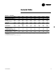
Electrical Data Table ED-1 — Electrical Data Unit Characteristics Nominal Tons 20 25 30 40 50 60 80 100 120 Condenser Fan Motor Model No. CAUC-C20G CAUC-C204 Electrical Characteristics 200-230/60/3 460/60/3 Allowable Voltage Range 180-220/208-254 416-508 Minimum Circuit Ampacity (3),(5) 9.2 4.1 Maximum Fuse Size (2),(5) 15 15 No./HP (1) 2/1.0 2/1.0 FLA (Ea.) (1) 4.1 1.
Dimensional Data (20 Ton) Figure DD-1 — CAUC-C20 Unit Dimensions, Recommended Clearances, Mounting Locations, Electric and Refrigerant Connection Sizes and Locations ACDS-PRC001-EN 13
Dimensional Data (25Ton) Figure DD-2 — CAUC-C25 Unit Dimensions, Recommended Clearances, Mounting Locations, Electric and Refrigerant Connection Sizes and Locations 14 ACDS-PRC001-EN
Dimensional Data (30 Ton) Figure DD-3 — CAUC-C30 Unit Dimensions, Recommended Clearances, Mounting Locations, Electric and Refrigerant Connection Sizes and Locations ACDS-PRC001-EN 15
Dimensional Data (40Ton) Figure DD-4 — CAUC-C40 Unit Dimensions, Recommended Clearances, Mounting Locations, Electric and Refrigerant Connection Sizes and Locations 16 ACDS-PRC001-EN
Dimensional Data (50 Ton) Figure DD-5 — CAUC-C50 Unit Dimensions, Recommended Clearances, Mounting Locations, Electric and Refrigerant Connection Sizes and Locations ACDS-PRC001-EN 17
Dimensional Data (60Ton) Figure DD-6 — CAUC-C60 Unit Dimensions, Recommended Clearances, Mounting Locations, Electric and Refrigerant Connection Sizes and Locations 18 ACDS-PRC001-EN
Dimensional Data (80 Ton) Figure DD-7 — CAUC-C80 Unit Dimensions, Recommended Clearances, Mounting Locations, Electric and Refrigerant Connection Sizes and Locations NOTES: 1. HOT GAS DISCHARGE AND LIQUID LINE CONNECTION LOCATIONS SHOWN IN THE FRONT VIEW DO NOT REPRESENT HOLES IN THE UNIT PANEL. ACCESS TO THESE CONNECTIONS ARE PROVIDED BY THE CUSTOMERS. 2. DIMENSIONAL TOLERANCE +/- 1/8”.
Dimensional Data (100Ton) Figure DD-9 — CAUC-C100 Unit Dimensions, Recommended Clearances, Mounting Locations, Electric and Refrigerant Connection Sizes and Locations 20 ACDS-PRC001-EN
Dimensional Data (120Ton) Figure DD-10 — CAUC-C120 Unit Dimensions, Recommended Clearances, Mounting Locations, Electric and Refrigerant Connection Sizes and Locations NOTES: 1. HOT GAS DISCHARGE AND LIQUID LINE CONNECTION LOCATIONS SHOWN IN THE FRONT VIEW DO NOT REPRESENT HOLES IN THE UNIT PANEL. ACCESS TO THESE CONNECTIONS ARE PROVIDED BY THE CUSTOMERS. 2. DIMENSIONAL TOLERANCE +/- 1/8”.
Weights Figure W-1 — 20-30 Tons Figure W-2 — 40-60 Tons Top View (Mounting Locations) Table W-1 — 20 to 60 Ton Weights (Lbs./Kg.) Nominal Tons 20 25 30 40 50 60 Operating Model Weight Number AL CU CAUC-C20 Lb. 1146 1348 Kg. 519.8 611.5 CAUC-C25 Lb. 1190 1394 Kg. 539.8 632.3 CAUC-C30 Lb. 1302 1585 Kg. 590.6 719.0 CAUC-C40 Lb. 2048 2366 Kg. 929.0 1073.2 CAUC-C50 Lb. 2280 2664 Kg. 1034.2 1208.4 CAUC-C60 Lb. 2465 3010 Kg. 1118.1 1365.3 Loc. 1 AL CU 320 371 145.2 168.3 329 378 149.2 171.5 353 414 160.
Mechanical Specifications General Options Factory-assembled and wired air cooled condensing unit. The unit frame is constructed of 14 gauge welded galvanized steel. Panels and access doors are 14 or 16 gauge galvanized steel. Unit surface is phosphatized and finished withTrane Slate Gray air-dry paint. This paint finish exceeds ASTMB117 500 hour continuous salt spray test. The unit coils are protected with steel louvered panels.
Literature Order Number The Trane Company Unitary Products Group 2701 Wilma Rudolph Blvd. Clarksville, TN 37040 www.trane.com An American Standard Company ACDS-PRC001-EN File Number PL-RF-ACDS-PRC0001-EN-04-2001 Supersedes ACDS-DS-1 07/00 Stocking Location Inland-LaCrosse Since The Trane Company has a policy of continuous product and product data improvement, it reserves the right to change design and specifications without notice.