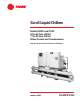
Scroll Liquid Chillers Model CGWF and CCAF 20 to 60 Tons (60 Hz) 17 to 50 Tons (50 Hz) Water-Cooled and Condenserless Built For the Industrial and Commercial Markets January 2004 CG-PRC012-EN
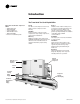
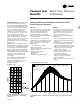
Introduction The Trane 20-60 Ton Scroll Liquid Chiller More Than Just Another “Improved” Chiller — Advanced Design — Better Reliability — Superior Efficiency — New CH530 Controls — Better Availability — Easier To Install and Operate Design The Trane scroll compressor is the most advanced scroll compressor in the industry. Reliability 64 percent fewer compressor parts, compared to reciprocating compressors, mean long and reliable life. Efficiency CGWF scroll chillers meet and exceed ASHRAE Standard 90.
Contents Introduction 2 Features and Benefits 4 World Class Efficiency and Reliability Options Controls 8 Application Considerations 12 Model Number 13 General Data 14 Selection Procedure 15 Performance Data 16 Full Load Performance Part Load Performance Adjustment Factors Pressure Drops Electrical Data and Connections 27 Typical Wiring Diagram Field Layout CG-PRC012-EN Dimensional Data 32 Weights 37 Mechanical Specifications 38 3
Features and Benefits Trane Value Means Fast Availability, Easy Installation and Quality Service Packed Stock For Fast Delivery When your project is a fast-track job, Trane can help. A wide range of chillers are stocked and can be shipped soon after receipt of your order. Build To Order Need a special chiller fast? Think Trane scroll chillers. New manufacturing technology and inventory control means the fastest delivery schedule in the industry.
Features and Benefits ASHRAE Standard 90.1 All Trane chillers meet and exceed the new efficiency levels mandated by ASHRAE Standard 90.1. This new standard requires higher efficiencies than past technologies can deliver. It mandates higher efficiency levels for scroll water chillers in comparison to reciprocating chillers. In fact, energy efficiency is so paramount the US Federal Government has adopted standard 90.1.
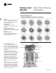
Features and Benefits World Class Efficiency & Reliability Trane Scroll Compressor — Maximum Efficiency with Enhanced Reliability General The scroll compressor has two scrolls. The top scroll is fixed and the bottom scroll orbits. Each scroll has walls in a spiral shape that intermesh. Inlet-First Orbit As the bottom scroll orbits, two refrigerant gas pockets are formed and enclosed. Compression-Second Orbit The refrigerant gas is compressed as the volume is reduced closer to the center of the scroll.
Features and Benefits Options Hot Gas Bypass: Hot gas bypass option allows unit operation below the minimum step of unit unloading. The regulator valve, along with all associated refrigerant piping and electrical wiring, are factory installed and tested on one refrigeration circuit. Unit does not start in hot gas bypass mode. If the unit operates in bypass mode for 30 minutes without a call for cooling, it will pump down and shut off. Unit starts immediately upon a further call for cooling.
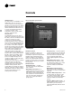
Controls Human Interfaces The Trane water-cooled 20-60 ton scroll CGWF chiller offers an easy-to-use operator interface panel, the DynaView. Figure C1. DynaView operator interface DynaView is an LCD touchscreen display that is navigated by file tabs. This is an advanced interface that allows the user to access any important information concerning setpoints, active temperatures, modes, electrical data, pressures, and diagnostics.
Controls Easy Interface to A Generic Building Management System Controlling the scroll CGWF chiller with building management systems is stateof-the-art, yet simple with either the LonTalk Communications Interface for Chillers (LCI-C) or Generic Building Management System Hardwire Points. Simple Interface with Other Control Systems CH530 controls afford simple interface with other control systems, such as time clocks, building automation systems, and ice storage systems.
Controls Tracer Summit controls — Interface With The Trane Integrated Comfort System (ICS) Trane Chiller Plant Control The Tracer Summit Chiller Plant Building Management System with Chiller Plant Control provides building automation and energy management functions through stand-alone control. The Chiller Plant Control is capable of monitoring and controlling your entire chiller plant system.
Controls Trane Chiller Plant Automation Trane’s depth of experience in chillers and controls makes us a well-qualified choice for automation of chiller plants using scroll liquid chillers. The chiller plant control capabilities of the Trane Tracer Summit® building automation system are unequaled in the industry. Our chiller plant automation software is fully pre-engineered and tested.
Application Considerations Unit Location Units should be installed indoors where exposure to rain or water splash is minimal. A level foundation or flooring must be provided which will support at least 150 percent of the operating weight of the unit. The chiller foundation must be rigid to reduce vibration transmission to a minimum. Use of vibration isolators is recommended for applications with sensitive vibration and noise criteria.
Model Number Description Model Number Description CGW F 020 4 C A0 U 1,2,3 4 5,6,7 8 9 10,11 12 A 13 Digits 01, 02, 03, – Chiller series CGWF = Water cooled scroll chiller CCAF = Scroll compressor chiller (condenserless) Digits 04, – Development sequence Digits 05, 06, 07 – Unit nominal tonnage 020 = 20 Nominal tons 025 = 25 Nominal tons 030 = 30 Nominal tons 040 = 40 Nominal tons 050 = 50 Nominal tons 060 = 60 Nominal tons Digit 08 – Unit voltage G = 208-230/60/3 D = 380/60/3 N = 400/50/3 4 = 460/60/3 5
General Data Table GD-1. General data — CGWF water-cooled chiller Size Compressor Quantity (1) Nominal Size (tons) (2) Steps of Unloading (%) Evaporator Water Storage (gallons) (liters) Min. Flow (gpm) (L/s) Max. Flow (gpm) (L/s) Condenser Water Storage (gallons) (liters) Min. Flow (gpm) (L/s) Max. Flow (gpm) (L/s) General Unit Refrigerant No. of Independent Refrigerant Circuits Refrigerant (pound) Charge (kilogram) Oil Charge (pints) (liters) 20 25 30 2 10/10 100,50 2 10/15 100,60 12 45 24 1.5 72 4.
Selection Procedures The chiller capacity tables on the following pages cover the most frequently encountered leaving water temperatures. For temperature drops other than 10°F [5.6°C], refer to Table SP-1, Performance Adjustment Factors, shown below. Additional chiller selections and performance information can be obtained through your local Trane sales office. To select a Trane water-cooled scroll chiller, the following information is required: 1. Design load in tons of refrigeration 2.
Performance Data Full Load Performance Table PD-1. 60 Hz CGWF performance data in English units Evaporator Leaving Water Temperature (F) 40 42 44 46 48 50 Unit Size 20 25 30 40 50 60 20 25 30 40 50 60 20 25 30 40 50 60 20 25 30 40 50 60 20 25 30 40 50 60 20 25 30 40 50 60 Tons 19.2 23.8 28.3 38.0 47.0 57.7 20.0 24.7 29.4 39.5 48.9 59.9 20.8 25.7 30.6 41.1 50.8 62.1 21.5 26.6 31.7 42.6 52.8 64.4 22.4 27.6 32.9 44.2 54.7 66.7 23.2 28.7 34.1 45.9 56.8 69.1 75 kW 13.8 17.2 20.7 27.3 34.1 42.1 13.
Performance Data Full Load Performance Table PD-2. 60 Hz CGWF performance data in Metric units Evaporator Leaving Water Temperature (C) 6 8 10 Unit Size 20 25 30 40 50 60 20 25 30 40 50 60 20 25 30 40 50 60 kWo 70.4 87.1 104.0 139.5 172.4 211.0 75.7 93.5 111.4 150.3 185.3 226.0 80.8 99.9 119.0 159.9 197.9 240.7 25 kWi 14.2 17.7 21.2 28.0 35.0 43.2 14.3 17.8 21.4 28.2 35.2 43.5 14.4 17.9 21.5 28.4 35.5 43.8 Entering Condenser Water Temperature (C) 30 COP kWo kWi COP kWo 5.0 67.7 15.5 4.4 64.7 4.
Performance Data Full Load Performance Table PD-3. 50 Hz CGWF performance data in English units Evaporator Leaving Wate Temperature (F) 42 44 46 48 50 Unit Size 20 20 25 30 40 50 60 20 25 30 40 50 60 20 25 30 40 50 60 20 25 30 40 50 60 20 25 30 40 50 60 Tons 19.2 16.8 20.7 24.6 33.2 41.0 50.4 17.4 21.5 25.6 34.5 42.6 52.3 18.1 22.4 26.6 35.8 44.3 54.2 18.8 23.2 27.6 37.2 45.9 56.1 19.5 24.1 28.6 38.6 47.6 58.1 75 kW 13.8 11.1 13.9 16.7 21.9 27.4 33.8 11.1 13.9 16.7 22.0 27.5 33.9 11.2 13.9 16.
Performance Data Full Load Performance Table PD-4. 50 Hz CGWF performance data in Metric units Evaporator Leaving Water Temperature (C) 6 8 10 Unit Size 20 20 25 30 40 50 60 20 25 30 40 50 60 20 25 30 40 50 60 kWo 70.4 59.4 73.4 87.3 117.6 145.3 178.4 63.7 78.6 93.5 126.0 155.6 190.4 68.1 84.0 99.9 134.8 166.4 203.0 25 kWi 14.2 11.4 14.2 17.0 22.4 28.0 34.5 11.4 14.3 17.1 22.5 28.2 34.7 11.4 14.3 17.2 22.6 28.3 34.9 Entering Condenser Water Temperature (C) 30 COP kWo kWi COP kWo 5.0 67.7 15.5 4.
Performance Data Full Load Performance Table PD-7.
Performance Data Full Load Performance Table PD-8. 60 Hz CCAF performance data in English units Evaporator Leaving Water Temperature (F) 48 50 Unit Size 20 20 25 25 30 30 40 40 50 50 60 60 20 20 25 25 30 30 40 40 50 50 60 60 Condenser Size CAUC-C20 CAUC-C25 CAUC-C25 CAUC-C30 CAUC-C30 CAUC-C40 CAUC-C40 CAUC-C50 CAUC-C50 CAUC-C60 CAUC-C60 CAUC-C80 CAUC-C20 CAUC-C25 CAUC-C25 CAUC-C30 CAUC-C30 CAUC-C40 CAUC-C40 CAUC-C50 CAUC-C50 CAUC-C60 CAUC-C60 CAUC-C80 Tons 21.3 21.7 26.5 27.0 31.6 32.2 42.4 42.8 52.
Performance Data Full Load Performance Table PD-9.
Performance Data Part Load Performance Table PD-5. Part-load performance for CGWF 20-60 ton – 60 Hz in English units Unit Size 20 25 30 40 50 60 Tons kW EER Tons kW EER Tons kW EER Tons kW EER Tons kW EER Tons kW EER 100% 19.9 15.2 15.5 24.5 19.0 15.4 29.2 22.8 15.3 39.4 30.1 15.6 48.6 37.6 15.4 59.4 46.5 15.2 IPLV 20.3 20.5 20.3 20.7 19.6 19.8 Notes: 1. IPLV values are rated in accordance with ARI Standard 550/590-98. 2. EER and IPLV values include compressor and control kW. 3.
Performance Data Adjustment Factors Figure PAF-1. Ethylene glycol performance adjustment factors Figure PAF-2.
Performance Data Adjustment Factors Figure PAF-3. Ethylene glycol and propylene glycol solution freezing points Table PAF-1. Pressure drop correction factor Leaving Water Temperature 0 10 20 30 40 50 60 0 NA NA NA NA 1.00 1.00 1.00 10 NA NA NA 1.15 1.12 1.09 1.05 Percent of Ethylene Glycol 20 30 NA NA NA 1.38 1.26 1.34 1.22 1.30 1.19 1.26 1.16 1.23 1.09 1.12 40 1.50 1.46 1.42 1.38 1.34 1.31 1.16 50 1.60 1.55 1.51 1.47 1.42 1.39 1.21 40 1.63 1.55 1.46 1.39 1.33 1.28 1.13 50 1.90 1.74 1.62 1.53 1.
Performance Data Pressure Drops Chart PD-1. CGWF evaporator Chart PD-2.
Electrical Data and Connections Table E-1.
Electrical Data Typical Wiring and Connections Diagram 28 CG-PRC012-EN
Typical Wiring Electrical Data and Connections Diagram CG-PRC012-EN 29
Electrical Data and Connections Field Layout 30 CG-PRC012-EN
Electrical Data and Connections Field Layout CG-PRC012-EN 31
Dimensional Data Size 20 Ton 25 Ton 30 Ton A 2" (51) 2" (51) 2 1/2" (64) B 8 1/2" (216) 8 1/2" (216) 7 3/4" (197) C 4'-8" (1423) 4'-8" (1423) 4'-6 1/2" (1384) CGWF 20-30 Ton D 1'-3 3/8" (391) 1'-3 3/8" (391) 1'-5 3/8" (441) E 4 1/8" (105) 4 1/8" (105) 2 1/4" (57) F 8 5/8" (218) 8 5/8" (218) 12" (305) G 5 5/8" (143) 5 5/8" (143) 8" (203) H 2' 7 3/8" (797) 2' 7 3/8" (797) 2' 8 3/16" (818) Notes: 1. Dimensions in ( ) are in millimeters. 2. Dimensional tolerance ± 1/4” (6.4). 3.
Dimensional Data Size 40 Ton 50 Ton A 2 1/2" (64) 3" (76) B 1'-3 3/4" (400) 1'-3 1/2" (394) CGWF 40-50 Ton C 6'-5 1/2" (1968) 6'-5" (1956) D 1'-4 1/4" (413) 1'-6 1/8" (480) E 4 3/8" (111) 2 1/2" (64) Notes: 1. Dimensions in ( ) are in millimeters. 2. Dimensional tolerance ± 1/4” (6.4). 3. These dimensions for left hand condenser connections.
Dimensional Data 34 CGWF 60 Ton CG-PRC012-EN
Dimensional Data Unit Size 20 Ton 25 Ton 30 Ton A 8 1/2” 8 1/2” 7 3/4” B 3’-11 1/2” 3’-11 1/2” 3’-10 3/4” Unit Size 20 Ton 25 Ton 30 Ton A 216 216 197 B 1207 1207 1187 CCAF 20-30 Ton English Dimensions C D 2” 2’-0” 2” 1’-11 3/4” 2 1/2” 2’-1 7/8” Metric Dimensions (mm) C D 51 610 51 603 64 657 E 1’-3 1/2” 1’-3 1/2” 1’-5 3/8” F 3’-3” 3’-10” 3’-10” E 394 394 441 F 1041 1041 1168 Notes: 1. Add 3/4” (19 mm) for units with insulation. 2. Dimensional tolerance ± 1/4” (6.4). 3.
Dimensional Data CCAF 40-60 Ton Unit Size 40 Ton 50 Ton 60 Ton A 5’-1 3/4” 5’-1 1/2” 5’-1 1/2” B 1’-3 3/4” 1’-3 1/2” 1’-3 1/2” English Dimensions C 1’-11 1/4” 2’-1 1/8” 2’-0 7/8” D 2 1/2” 3” 3” E 3’-5” 3’-10” 3’-10” F 1’-4 1/4” 1’-6 1/8” 1’-6 1/8” Unit Size 40 Ton 50 Ton 60 Ton A 1568 1562 1562 B 400 394 394 Metric Dimensions (mm) C 591 638 632 D 64 76 76 E 1041 1168 1168 F 413 480 460 Notes: 1. Dimensions in ( ) are in millimeters. 2. Add 3/4” (19 mm) for units with insulation. 3.
Weights Table W-1. Weights, CGWF chillers Unit Operating Wt. Shipping Wt. (pounds) (kilogram) (pounds) (kilogram) 20 1694 768 1522 690 25 1757 797 1600 726 30 2249 1020 2014 914 40 2746 1246 2366 1073 50 2977 1350 2626 1191 60 3905 1771 3376 1531 30 1274 579 1836 834 40 1509 685 1792 814 50 1808 821 2166 984 60 1982 900 2494 1133 Table W-2. Weights, CCAF compressor chillers Unit Operating Wt. Shipping Wt.
Mechanical Specifications General All scroll chillers are factory tested and monitored for power and control operation (CGWF only). CGWF units ship with a full operating charge of refrigerant and oil. CCAF units ship with a full operating charge of oil. Exposed surfaces are painted with an air-dry beige primer-finisher prior to shipment.
Mechanical Specifications DynaView Panel Factory-mounted to the control panel door, the operator interface has an LCD touch-screen display for operator input and information output. This interface provides access to the following information: evaporator report, condenser report, compressor report, ASHRAE Guideline 3 report, main, chiller, feature setting, manual control setting and display setting. All diagnostics and messages are displayed in “clear language.
Literature Order Number CG-PRC012-EN File Number CG-PRC012-EN 104 Trane A business of American Standard Companies www.trane.com Supersedes CG-PRC011-EN 102 Stocking Location Inland For more information contact your local sales office or e-mail us at comfort@trane.com Trane has a policy of continuous product and product data improvement and reserves the right to change design and specifications without notice.