
User's Manual


19
CTV-PRC007-EN
Free Cooling
Unit
Options
Temperature and humidity control
requirements are important
considerations when evaluating the use
of CenTraVac free cooling. Low
temperature outside air (from the
outside air economizer) often requires a
large amount of energy for
humidification purposes. Free cooling
operation helps to reduce these
humidification costs on many
applications.
It is important to note that those
applications which require extremely
precise humidity control typically cannot
tolerate warmer than design chilled
water temperatures. Therefore, since
free cooling chillers normally deliver
warmer than design chilled water
temperatures, free cooling operation is
usually not applicable with systems
which require precise humidity control.
Also, free cooling is generally not used in
conjunction with heat recovery systems,
since mechanical cooling must be used
to recover heat that will be used
elsewhere in the building for
simultaneous heating.
Operation
Free cooling operates on the principle
that refrigerant flows to the area of
lowest temperature in the system. The
Tracer
™
system/Chiller Plant Manager
(CPM) can be used for automatic free
cooling control. When condenser water
is available at a temperature lower than
the required leaving chilled water
temperature, the CPM starts the free
cooling cycle. If the load cannot be
satisfied with free cooling, the CPM
or a customer supplied system can
automatically switch to the powered
cooling mode. If desired, the chiller
can be manually switched to the free
cooling mode at the unit control panel.
Upon changeover to free cooling, the
shutoff valves in the liquid and gas lines
are opened and a lockout circuit
prevents compressor energization.
Liquid refrigerant drains by gravity from
the storage tank into the evaporator,
flooding the tube bundle. Since the
refrigerant temperature and pressure
will be higher in the evaporator than in
the condenser, due to the water
temperature difference, the refrigerant
gas boiled off in the evaporator will flow
to the condenser. The gas then
condenses and flows by gravity back to
the evaporator. This automatic
refrigeration cycle is sustained as long as
a temperature difference exists between
the condenser water and evaporator
water.
The difference in temperature between
the condenser and evaporator
determines the rate of refrigerant flow
between the two shells and hence the
free cooling capacity.
If the system load becomes greater than
the free cooling capacity either the
operator manually stops free cooling, a
binary input from a customer-supplied
system disables free cooling or the CPM
can automatically perform this function.
The gas and liquid valves close and the
compressor starts. Refrigerant gas is
drawn out of the evaporator by the
compressor, compressed and introduced
into the condenser. Most of the
condensed liquid first takes the path of
least resistance by flowing into the
storage tank which is vented to the high
pressure economizer sump by a small
bleed line. When the storage tank is
filled, liquid refrigerant must flow
through the bleed line restriction. The
pressure drop through the bleed line is
greater than that associated with the
orifice flow control device, hence liquid
refrigerant flows normally from the
condenser through the orifice system
and into the economizer.
The free cooling accessory consists of
the following factory-installed or
supplied components:
•
A refrigerant gas line, including an
electrically actuated shutoff valve,
installed between the evaporator and
condenser.
•
A valved liquid return line including an
electrically activated shutoff valve,
between the condenser sump and
evaporator.
•
A liquid refrigerant storage vessel.
•
Added refrigerant charge.
•
Manual free cooling controls on the
unit control panel.
For specific information on free cooling
applications, contact the local Trane sales
office.
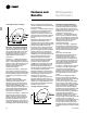
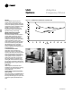
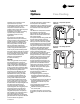
Figure O-5 — Compressor Operation
Schematic
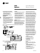
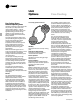
Figure O-6 — Free Cooling Operation
Schematic