Installation Operation Maintenance Tracer™ UC400 Programmable BACnet Controller For Factory Installation on Variable Air Volume (VAV) Units May 2010 VAV-SVX07A-EN
Warnings, Cautions and Notices Warnings, Cautions and Notices. Note that warnings, cautions and notices appear at appropriate intervals throughout this manual. Warnings are provide to alert installing contractors to potential hazards that could result in personal injury or death. Cautions are designed to alert personnel to hazardous situations that could result in personal injury, while notices indicate a situation that may result in equipment or property-damage-only accidents.
Table of Contents General Information . . . . . . . . . . . . . . . . . . . . . . . . . . . . . . . . . . . . . . . . . . . . . . . . . . . . 5 Tracer UC400 BACnet Unit Controller . . . . . . . . . . . . . . . . . . . . . . . . . . . . . . . . . 5 Shipping & Storage . . . . . . . . . . . . . . . . . . . . . . . . . . . . . . . . . . . . . . . . . . . . . . . . 6 Specifications . . . . . . . . . . . . . . . . . . . . . . . . . . . . . . . . . . . . . . . . . . . . . . . . . . . . .
Airflow Failure Troubleshooting Procedures . . . . . . . . . . . . . . . . . . . . . . . . . . 75 Supply/Discharge Air Temp Sensor Failure Troubleshooting Procedures . 77 CO2 Sensor Failure Troubleshooting Procedures . . . . . . . . . . . . . . . . . . . . . . 78 VAV Damper Failure Troubleshooting Procedures . . . . . . . . . . . . . . . . . . . . . 79 VAV Series Fan Failure Troubleshooting Procedures . . . . . . . . . . . . . . . . . . 80 VAV Parallel Fan Failure Troubleshooting Procedures . . . . . . . .
General Information This chapter contains information about the following: • Tracer™ UC400 BACnet Unit Controller • Shipping & Storage • Specifications • Tracer UC400 Controller Enhancements • Tracer UC400 Controller Features Tracer UC400 BACnet Unit Controller The Tracer UC400 controller is a programmable general purpose BACnet, microprocessor-based, Direct Digital Controller (DDC).
General Information Shipping & Storage Each VAV order ships with service literature. When unpacking, make sure that the literature is not lost or discarded with the packing material. Visually inspect the individual components for obvious defects or damage. All components are thoroughly inspected before leaving the factory. Any claims for damage incurred during shipment must be filed with the carrier.
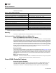
General Information Universal Inputs UI1 and UI2 • UI1: Spare, but recommended for Relative Humidity. Resistive/thermistor inputs, 0-10VDC inputs, or 4-20 mA inputs. Current Mode Impedance: 200 ohm. Voltage Mode Impedance: 10 kohm min. • UI2: Spare, but recommended for CO2. Resistive/thermistor inputs, 0-10VDC inputs, or 4-20 mA inputs. Current Mode Impedance: 200 ohm. Voltage Mode Impedance: 10 kohm min. Pressure Inputs P1 and P2 • P1: Supply air flow; pressure transducer: From 0 to 2 in.
General Information ICES-003, Issue 4:2004 Table 2. Agency listings/compliance Standard Test Level EN 61326-1: 2006 Electrical equipment for measurement, control and laboratory use - EMC requirements, part 1: General Requirements.
General Information Flow Tracking The Tracer™ UC400 controller is designed with the ability to be applied in flow tracking applications. This allows the controller to be paired with one of its peers to mirror the flow of the lead unit, with or without an offset (positive or negative static pressure as desired). Ventilation Flow Control with Tempering The Tracer UC400 controller is designed with the ability to be applied in ventilation flow control applications.
General Information Flash Download The Tracer™ UC400 controller has been designed with flash memory. This allows the option of upgrading the controller in the field (features, corrections to defects) without changing out the controller. Trane Controller Compatibility The Tracer UC400 controller is a BACnet-compliant controller. As such, the controller is compatible with the latest generation of Trane controls.
General Information Temperature Statistics As a part of the standard application, both the VAS and Area applications calculate the minimum space temperature (and source), maximum space temperature (and source), and the average space temperature. Tracer™ UC400 Controller Compatibility The Tracer UC400 controller integrates with other BACnet systems and devices using BACnet MS/ TP.
VAV Start Up/Check Out Procedure This chapter contains information about the following: • Tracer™ UC400 Controller Pre-Power Check-Out • Tracer UC400 Controller Power Wiring • Communication Wiring • Space Temperature Control Wiring • Zone Sensor Wiring • Duct Temperature Sensor Wiring • Binary Input Wiring • Binary Output Wiring • Zone Sensor Check-Out • Ventilation Flow Control • Flow Tracking Control • Wireless Zone Sensor Tracer UC400 Controller Pre-Power Check-Out WARNING Live Electri
VAV Start Up/Check Out Procedure Tracer UC400 Controller Power Wiring Power Requirements WARNING Hazardous Voltage! Disconnect all electric power, including remote disconnects before servicing. Follow proper lockout/tagout procedures to ensure the power can not be inadvertently energized. Failure to disconnect power before servicing could result in death or serious injury.
VAV Start Up/Check Out Procedure LED Description and Behavior There are 15 LEDs on the front of the Tracer UC400 controller. Figure 1, p. 14 shows the locations of each LED and describes the behavior of each. Tracer UC400 Controller Module Figure 1. LED locations Marquee LED LINK IMC TX RX SERVICE BO1 BO2 BO3 BO4 BO5 BO6 BO7 BO8 BO9 LED Description and Operation There are 15 LEDs on the front of the Tracer UC400 controller. Figure 1, p.
VAV Start Up/Check Out Procedure Communication Wiring WARNING Electrocution and Fire Hazards with Improperly Installed and Grounded Field Wiring! Improperly installed and grounded field wiring poses FIRE & ELECTROCUTION hazards. To avoid these hazards, you MUST follow requirements for field wiring installation and grounding as described in NEC and your local/state electrical codes. All field wiring MUST be performed by qualified personnel.
VAV Start Up/Check Out Procedure Rotary Switches There are three rotary switches on the font of the Tracer™ UC400 controller device that are used to define a three-digit address when the Tracer TU service tool is installed on a BACnet communications network. The three-digit address setting is used as both the BACnet MAC address and the BACnet device ID. Note: Valid MAC addresses are 001 to 120 for BACnet. Figure 3.
VAV Start Up/Check Out Procedure Space Temperature Control Wiring Zone Sensor Hardwired Option Depending on the zone sensor options used, a maximum of seven wires may be required to run from the Tracer™ UC400 controller to the zone sensor. The zone sensor options are: • Zone sensor (temperature only) - Part Number X1351152801. • Zone sensor with timed override (TOV) on/cancel button - Part Number X1351153001. • Zone sensor with adjustable setpoint thumbwheel - Part Number X1351152901.
VAV Start Up/Check Out Procedure Figure 4.
VAV Start Up/Check Out Procedure Figure 5.
VAV Start Up/Check Out Procedure Zone Sensor Wiring Location and Mounting A zone sensor in each control zone should be located in the most critical area of the zone. Sensors should not be mounted in direct sunlight or in the area's supply air stream. Subdivision of the zone may be necessary for adequate control and comfort. Avoid mounting zone sensors in areas subject to the following: • Drafts or "dead spots" behind doors or corners. • Hot or cold air ducts. • Radiant heat from the sun or appliances.
VAV Start Up/Check Out Procedure Figure 6. Duct temperature sensors: upstream/downstream Binary Input Wiring Each Tracer™ UC400 controller provides three binary inputs. On the Tracer UC400 controller factory-installed controller, one of the binary inputs is configured in the factory for occupancy. The binary inputs can be configured with the Tracer TU service tool for occupancy or other use. The input associates 0 VAC with open contacts and 24 VAC with closed contacts.
VAV Start Up/Check Out Procedure Wireless Zone Sensor The Trane Wireless Zone Sensor set includes a sensor and a receiver that work together to provide the same functions as the equivalent Trane wired sensor, such as the standard 10k Ω temperature input (with the exception of the communication jack). No further software or hardware is necessary for site evaluation, installation, or maintenance.
VAV Start Up/Check Out Procedure Figure 8. Mounting hole dimensions for sensor 3.27 in (8.30 cm) 2.36 in (6.00 cm) 1.34 in (3.41 cm) Note: The dimensions are the same for both the sensor and the receiver. Setting the Address, Mounting, Wiring, and Associating the Receiver and Sensor The following procedure list shows the recommended order for installation: VAV-SVX07A-EN • Choosing a Location for Mounting the Sensor. • Setting the Rotary Address Switches on the Receiver and on the Sensor.
VAV Start Up/Check Out Procedure Choosing a Location for Mounting the Sensor Placement of the receiver and the sensor set is critical to proper operation. In most installations, distance is not the limiting factor for proper radio signal quality. It is more greatly affected by walls, barriers, and general clutter. For best radio transmission range and reliability, wherever possible, mount the receiver and sensor in line of sight. Try to minimize the number of barriers between the pair of devices.
VAV Start Up/Check Out Procedure Figure 9. Setting the rotary address switches on the receiver and the sensor Do not remove the insulation strip yet.
VAV Start Up/Check Out Procedure 3. Make a notation of the address and location of the sensor. Factory Wiring of the Receiver to the VAV Unit Controller The required power for the receiver is 24 VAC or 24 Vdc and is less than 1 VA. The receiver is designed to be powered by the Tracer™ UC400 controller. Please see Figure 4, p. 18 and Figure 5, p. 19 for wiring details. Note: A dedicated transformer is not necessary or advised. Note: The receiver is factory mounted and field wiring is not necessary.
VAV Start Up/Check Out Procedure Applying Power to the Receiver Restore power to the unit controller. Observe LED5 on the receiver (Figure 11, p. 27). It will light and stay constantly On when 24 V power is normal. Figure 11. LED5 stays on after applying power to the receiver LED5 stays constantly On Receiver Indicates Readiness to Associate After initial power up, the receiver conducts a channel scan for 10 seconds.
VAV Start Up/Check Out Procedure Powering the Sensor and Associating the Sensor to the Receiver 1. Verify that the sensor is set to the same address as the receiver it is to be associated with. 2. Remove the insulation barrier, which is a plastic strip located between the two batteries (Figure 13, p. 28). Association will automatically occur between the sensor and the receiver.
VAV Start Up/Check Out Procedure Testing Signal and Battery Strength The following recommended test indicates signal and battery strength. It verifies that the association process was successful and that the batteries have adequate charge. (For more information on LEDs, see "Troubleshooting" chapter.) 1. Firmly press and release the Test button (S5) on the bottom of the sensor (Figure 14, p. 29). 2. View LED1, LED2, and LED3 to determine the strength of the signal.
VAV Start Up/Check Out Procedure Note: Not all features are applicable to VAV units. The building owner or operator may choose to limit tenant access to certain features. This can be done through configuration. Or, if a sensor is configured to match all control capabilities of the building automation system, the locking feature can be used to restrict the tenant from making changes. Configuration Procedure To configure settings on the model WDS sensor, follow this procedure in the order presented. 1.
VAV Start Up/Check Out Procedure Figure 17. Center button 3. Configure the sensor options in the order shown in Figure 18, p. 31. Review the display to ensure that you have selected the correct configuration options. • Press or • Press to scroll to the next selection. or to move to the next menu. Figure 18. Wireless configuration Setting Configuration options Temperature • Choose Fahrenheit or Celsius • Choose the degree resolution (whole degrees, half degrees, or tenths of degrees). . . . .
VAV Start Up/Check Out Procedure Setting Configuration options System (continued) b) Dual setpoint Note: N/A for VAV. emergency heat/ heat/cool/auto/off heat/cool/ auto/off emergency heat/ heat/cool/off c) No setpoint Note: N/A for VAV. no system options enabled Fan Note: Tracer UC400 controller does not use this to control the fan in a VAV fan-powered unit.
VAV Start Up/Check Out Procedure Figure 19. The example shows a display that has been configured for: • Dual setpoint • Temperature units (Fahrenheit) • Temperature resolution to tenths of a degree • System settings: Heat, Cool, Off • Fan Settings: Auto and On • Occupied/unoccupied option enabled To return the display to operating mode, press the configuration button (See Step 1). The following example shows a configured display in operating mode.
VAV Start Up/Check Out Procedure Optional Features Displaying Setpoint or Temperature You can configure the sensor to display either the temperature (default) or setpoint. To select either option: 1. Verify that the sensor is in operating mode and at the home screen. 2. Press the up and down arrows for 3 seconds. The arrow indicates setpoint display, as shown in Figure 22, p. 34. Figure 22.
VAV Start Up/Check Out Procedure Figure 24. If you try to access a feature that is locked, the lock symbol will appear on the displays. If you press a keypad button to try and change a locked setting, the locked symbol will flash.
Tracer™ UC400 Controller Operations This chapter contains information about the following: • Connecting with Tracer TU Service Tool • Status Button • Data Log Button • Controller Settings Button • Equipment Settings Button Connecting with the Tracer TU Service Tool The Tracer TU service tool is a service tool that allows parameters to be viewed or adjusted in the Tracer UC400 controller.
Tracer™ UC400 Controller Operations 5. The Tracer TU service tool Connect dialog box will appear. Choose the Direct Connection (Via USB cable) radio button and click Connect. Figure 26. Connect screen Status Button Figure 27. Status button The Status button is the first utility button that can be selected and has six section tabs available for the selected device and utility. Unit Summary Tab The Tracer TU service tool will launch and display the status of the Tracer UC400 controller.
Tracer™ UC400 Controller Operations Connected to: Describes the type of device being communicated to via Tracer TU service tool. It also indicates the general program that has been placed in controller and if communication is up. The two states for communication are Configured On line or Not Communicating. Alert Boxes Points Out of Service: Indicates the number of points that are currently set to Out of Service. Active Alarms: Indicates the number of active alarms requiring your attention.
Tracer™ UC400 Controller Operations closes the air valve if the configured airflow tracking offset is negative for flow tracking control units. If the configured airflow tracking offset is positive, the controller opens the air valve to the configured maximum airflow. Once a valid differential pressure is established through the local hardwired input and no longer present, the controller generates a flow sensor failure diagnostic.
Tracer™ UC400 Controller Operations Grid Columns Index: Displays the sequence number assigned to the point. Name: Displays the name of the point. Value: Displays the current or assigned value of the point. Units: Displays the units of measure in which the point is expressed. State: Displays the state of the point. Point states are Normal, Out of Service, Fault, Locked, and Alarm. Control: Click to bring up the Override Request dialog box on which you can change the state of the point.
Tracer™ UC400 Controller Operations Point Name: Displays the name of the affected point. Description: Displays a short description of what occurred. Acknowledgement Required: Indicates whether or not the alarm has to be acknowledged at the parent Tracer SC level. Controller Status Tab BAS Communication: Displays the status of the communications network.
Tracer™ UC400 Controller Operations • Export captured data to various file formats in third-party software tools. • Save graphs as image files. View Graphs Tab The View Graphs tab contains controls used to set up and generate graphs (line charts) presenting a subgroup of logged data points. You can use the predefined templates, or you can define your own custom graphs. You can also save your graph definition as a new template.
Tracer™ UC400 Controller Operations Show Legend: Use this check box to show and hide the legend that displays the corresponding color of each data point. Stop Graph: Use this button to halt graphing when you have sufficient data for your purposes. Session Log Tab You can use the Tracer TU Data Logging Utility to capture live data from a controller at a specified sampling rate. You can then graph subsets of the captured data in one or more graphs.
Tracer™ UC400 Controller Operations Copy: Use this option to copy an existing data log definition under a different name and then modify it to avoid extra typing. Edit: Use this option to edit an existing data log definition. The Data Log Properties dialog box appears. Delete: Use this option to delete one or more data logs after you are finished with them. Go button: Click this button to put the option you selected on the Actions drop-down list into effect.
Tracer™ UC400 Controller Operations To eliminate just a few items from a predefined category, first transfer all of the items to the Selected Data box using the double arrow and then eliminate any items from the Selected Data box by transferring them back to Available Data using the single left arrow button or by pressing Ctrl and making selections with your mouse.
Tracer™ UC400 Controller Operations Grid Columns Index: Displays the sequence number assigned to the point. Name: Displays the name of the point. Reference: Identifies the source or target of information supplied to or from the point. Locked: Indicates if the point is locked (not modifiable). State: Displays the current state of the point. (Point states are Normal, Out of Service, Fault, and Alarm.) Save: Saves the points to the controller.
Tracer™ UC400 Controller Operations Modify Default Units: Use these drop-down lists to change the default units of measure displayed for various device inputs or capabilities, such as Temperature, Gaseous Pressure, Fluid Pressure, Cooling Capacity, and so on. To set the controller units of measure 1. Click the Units expanding box. 2. Select your preferred Number Format from the Number Format drop-down list. 3.
Tracer™ UC400 Controller Operations Equipment Settings Button Figure 30. Equipment settings button On this button, you can set in the Tracer UC400 controller setpoints and other settings, as well as configure the controller parameters. You can change a number of equipment setpoints and setup parameters from the Equipment Utility screens. Scroll down through the expanding boxes to locate the setpoints you need to change. Setpoints Tab 1. Selecting a value from a drop-down list. 2.
Tracer™ UC400 Controller Operations the occupied standby mode when a communicated occupancy mode request (from a communicated occupancy override, occupancy schedule, or occupancy sensor) is combined with an unoccupied request from the local (hardwired) occupancy binary input. Note: This setpoint allows inactive spaces in the occupied mode to float to a more energy saving setpoint until occupancy mode deems it necessary to use another setpoint as its active setpoint.
Tracer™ UC400 Controller Operations AirFlow Gain: The airflow gain is used to calibrate the value reported by the flow sensor so that the reported airflow matches the actual airflow. The flow gain is determined during the air balancing process. A testing, adjusting, and balancing professional will use the TU Service Air and Water Balancing tool to calculate this value and balance the VAV box. Normally, you should not need to change this value here.
Tracer™ UC400 Controller Operations controller maintains the flow rate at the heating maximum airflow. This is normally used with a rooftop unit with staged heat that needs a Max constant volume of air movement to keep the heat exchanger from overheating and tripping the heat in the rooftop unit tripping on a high limit safety.
Tracer™ UC400 Controller Operations 6. Select Drive to Maximum Flow Position and allow sufficient time for the VAV damper to fully open. 7. Enter the Current Discharge Airflow value in the MAX CFM field (blue) under Tracer UC400 controller Measurement on the spreadsheet. 8. Measure the actual airflow with the flow hood. (Add the totals if more than one diffuser is present.) 9. Record them in the MAX CFM field under Flow Hood Measurement. 10.
Sequence of Operation This chapter contains information about the following: • Calibration • Occupancy Modes • Space Temperature Control Single Duct/Fan-Powered Units • Ventilation Flow Control • Flow Tracking Calibration Sequence The calibration sequence enables the controller to calibrate the air valve position and the water valve position. Calibration takes place if autocalibration is enabled and either a power cycle or a transition from occupied to unoccupied has occurred.
Sequence of Operation Unoccupied Mode Unoccupied mode (also known as night setback) is the normal operating mode for unoccupied spaces or nighttime operation. Unoccupied setpoints enable or disable occupied space temperature control. When the controller is in the unoccupied mode and configured for space temperature control, the controller attempts to keep the space temperature between the active unoccupied heating setpoint and the active unoccupied cooling setpoint.
Sequence of Operation Space Temperature Control Single Duct/Fan-Powered Units Space Temperature Single Duct Units Space Temperature Control Mode Space temperature control (STC) is one of three supported control algorithms. Space temperature control requires a valid space temperature. If there is no valid space temperature (communicated or local), the space temperature control algorithm does not run; the unit either shuts down or goes to construction mode.
Sequence of Operation Note: Heating operation and Reheat are two different entities. Air Valve Control in Space Temperature Control Operation Air delivered to the space is controlled with a three-wire, floating-point actuator that modulates the air valve. The controller positions the modulating air valve to deliver the desired airflow (cooling or heating capacity). The desired airflow is called the active-flow setpoint.
Sequence of Operation • Stage 1 is energized when the space temperature falls below the active heating setpoint and minimum airflow requirements are met. When the zone temperature rises above the active heating setpoint by 0.5°F (0.28°C), stage 1 is de-energized. • Stage 2 energizes when the space temperature is 1°F (0.56°C) or more below the active heating setpoint, and is de-energized when the space temperature is 0.5°F (0.28°C) below the active heating setpoint.
Sequence of Operation Table 6. Local heat only with no fan present (continued) Configuration Local Method of control Remote Stage 1 Not applicable On/Off hot water (1 stage) Stage2 Local thermostatic On: Zt < HSP Off: Zt ≥ HSP + 0.5°F (0.
Sequence of Operation Space Temperature Fan-Powered Units The Tracer™ UC400 controllers provide three fan options when in space temperature control mode: • One-speed ON/OFF series fan; • One-speed ON/OFF parallel fan; and • Flow control parallel fan. This controller supports an electronically commutated motor (ECM). The controller turns the ECM fan On and Off. It does not change dynamically the ECM fan airflow. To assist with flow balancing the fan flow rate is stored as a configuration item.
Sequence of Operation Parallel fan operation during calibration During calibration, the parallel fan is in the same state (ON or OFF) as it was before calibration started. It remains in that state until one minute after calibration ends. One minute after calibration ends, normal control of the parallel fan resumes. The one-minute period is ignored if reheat is active or if the parallel fan is overridden. Fan Off Delay There is a 15-second fan OFF delay.
Sequence of Operation ventilation purposes, a constant volume of fresh air can be maintained, regardless of small fluctuations in inlet static pressure. Ventilation flow control unit can use a Ventilation Setpoint from a BAS system if it is valid. If unit is stand alone the ventilation flow control uses one of the following two airflow setpoints: • If no reheat being used, it uses the configured Ventilation Setup Occupied Setpoint.
Sequence of Operation occupied operation, the control algorithm indirectly provides freeze protection. See Table 9, p. 62 for Unoccupied VFC control. Note: See BAS-SVX20*-EN for details on BAS system control of the Tracer™ UC400 controller. Stand-alone Controller Freeze Protection Controllers operating without communications do not have the source temperature available to them.
Sequence of Operation air valve. The controller positions the modulating air valve to deliver the desired airflow (cooling or heating capacity). The desired airflow is called the active flow setpoint. Flow tracking control is provided by two controllers working together: space temperature controller and flow tracking controller. The space temperature controller outputs the airflow as reported airflow.
Troubleshooting WARNING Live Electrical Components! During installation, testing, servicing and troubleshooting of this product, it may be necessary to work with live electrical components. Have a qualified licensed electrician or other individual who has been properly trained in handling live electrical components perform these tasks. Failure to follow all electrical safety precautions when exposed to live electrical components could result in death or serious injury.
Troubleshooting Table 10.
Troubleshooting • Blinks red when an alarm exists. LINK • The TX LED blinks green at the data transfer rate when the Tracer™ UC400 controller transfers data to other devices on the link. • The RX LED blinks yellow at the data transfer rate when the Tracer UC400 controller receives data from other devices on the link. IMC Not used. Service Shows solid green when pressed. BO1 to BO9 Shows solid Yellow when corresponding binary output is on. Green Service LED Table 11, p.
Troubleshooting 2. Check for short. • Remove all wires from controller except incoming power. • Check device using Tracer™ TU service tool to see if the Tracer UC400 controller is operating properly. If it does operate properly check inputs/outputs for a short. 3. Check for alarms or diagnostics with Tracer TU service tool. 4. For final step check program by downloading good program using Tracer TU service tool.
Troubleshooting 3. Check for alarms or diagnostics with Tracer TU service tool, and check that the communication link avoids interference. • Communication link should not be routed near or with any voltage source. • BACnet Wiring Best Practices. The following wiring practices are recommended: • Strip no more than 2 inches (5 cm) of the outer conductor of shielded wire. • Avoid sharing 24 VAC power between unit controllers. • Ensure that 24 VAC power supplies are consistently grounded.
Troubleshooting • Disconnect the zone sensor terminal plug from the Tracer™ UC400 controller and using an Ohmmeter, measure the resistance across the terminals 1 and 2. Compare the resistance to temperature using Table 12, p. 69. The resistance should shown value should be within ± 2 degrees near those measured with an accurate temperature measuring device. If not, the zone sensor needs to be replaced. 4. Verify that the wiring or the Tracer UC400 controller are not defective.
Troubleshooting Wired Zone Setpoint Failure Troubleshooting Procedures WARNING Hazardous Service Procedures! The maintenance and troubleshooting procedures recommended in this section of the manual could result in exposure to electrical, mechanical or other potential safety hazards. Always refer to the safety warnings provided throughout this manual concerning these procedures.
Troubleshooting In the event that the Tracer™ UC400 controller reports an incorrect zone temperature or setpoint, properly inspect the receiver for all models has four LEDs: LED1, LED2, LED3, and LED5. Figure 32, p. 71 shows their locations. Figure 32. LED locations on the receiver LED1 LED2 LED3 LED5 The sensor for models WTS and WZS have four LEDs: LED1, LED2, LED3, and LED5. The sensor for model WDS has test symbols and error codes that appear on the display. All three sensor models have a Test button.
Troubleshooting Table 13.
Troubleshooting • Model WDS: Battery life ("Testing Battery Status," Table 16, p. 73) and signal strength ("Testing Signal Strength," Table 17, p. 73) are indicated. Table 16. Battery status: Battery symbol on model WDS sensor display User action Battery test symbol Press Test button X Indicates… Full battery power 50% battery life left 25% battery life left. Replace batteries. Flashing symbol indicates that approximately 14 days of operation remain before the battery is too weak to power the sensor.
Troubleshooting WARNING Hazardous Service Procedures! The maintenance and troubleshooting procedures recommended in this section of the manual could result in exposure to electrical, mechanical or other potential safety hazards. Always refer to the safety warnings provided throughout this manual concerning these procedures. When possible, disconnect all electrical power including remote disconnect and discharge all energy storing devices such as capacitors before servicing.
Troubleshooting • Press the Test button (S5) on the sensor to force re-association. Confirm association and communication by noting LED1, LED2, and LED3 as described in "Signal Quality Test." • Pressing the Test button (S5) on the sensor initiates a signal quality test. LED1, LED2, and LED3 respond on the receiver by indicating excellent, marginal, or poor signal quality See Table 17, p. 73. The Sensor LED's or LCD can be observed and verified using Table 17, p. 73.
Troubleshooting • Tracer™ TU service tool will indicate that calibration is taking place by a calibration percent complete indicator. • When calibration is complete, the box will release to auto. Drive the box open to make sure that the box is not below 5% of its cataloged CFM. The controller is accurate in reading flow from 5% to 110% of cataloged CFM. • Release the box to auto and perform any necessary balancing work. See Tracer TU Help for balancing details.
Troubleshooting 4.50 volts DC and 5.50 volts DC (5 volts DC cataloged). If voltage not available replace the Tracer UC400 controller. • Remove the high and low tubes from the transducer (to simulate no flow). Read the transducer output voltage on P1 of the Tracer UC400 controller between the green and the black wires with a voltmeter. The voltage should be between 0.20 volts DC and 0.30 volts DC (0.25 volts DC is the null voltage output of the transducer indicating zero flow).
Troubleshooting sensor or AI5 and for supply air temperature sensor and measure the VDC. It should be 5VDC. If you have 5VDC at the Tracer™ UC400 controller the wires going to the zone have an open. If 5VDC is not present check incoming power to the UC400 on XFMR 24 VAC input and . Voltage should measure 24 VAC ± 10%. If you measure the proper voltage at XFMR 24 VAC input and and no voltage at AI4 and for discharge air temperature sensor or AI5 and for supply air temperature sensor.
Troubleshooting VAV Damper Failure Troubleshooting Procedures WARNING Hazardous Service Procedures! The maintenance and troubleshooting procedures recommended in this section of the manual could result in exposure to electrical, mechanical or other potential safety hazards. Always refer to the safety warnings provided throughout this manual concerning these procedures.
Troubleshooting • Damper should drive closed. Note: The Tracer™ UC400 controller outputs are switched to ground. Do not jumper 24 VAC to BO8 and BO9 because damage will occur. • If damper actuator does not open or close replace actuator. VAV Series Fan Failure Troubleshooting Procedures WARNING Hazardous Service Procedures! The maintenance and troubleshooting procedures recommended in this section of the manual could result in exposure to electrical, mechanical or other potential safety hazards.
Troubleshooting Notice: Equipment Damage! The Tracer UC400 controller outputs are switched to ground. Do not jumper 24 VAC to Binary output TRIAC(s) because damage will occur. 6. After all checks have been completed, check motor fan winding integrity and bearing failure.
Troubleshooting • Check BO4 to common . Should have 24 VAC; if it does not, measure the power input to on XFMR 24 VAC input and of the Tracer™ UC400 controller. The supply voltage should be between 20 and 28 VAC (24 VAC cataloged). However, voltages at either extreme may result in system instability. • Triac can be checked with purchasing a 24 VAC LED and see if it lights up on call for fan the Tracer UC400 controller. If LED does not light up replace the Tracer UC400 controller.
Troubleshooting VAV Electric Heat Stage(s) Failure Procedures WARNING Live Electrical Components! During installation, testing, servicing and troubleshooting of this product, it may be necessary to work with live electrical components. Have a qualified licensed electrician or other individual who has been properly trained in handling live electrical components perform these tasks.
Troubleshooting VAV Proportional Hot Water Failure Troubleshooting Procedures Check binary outputs WARNING Live Electrical Components! During installation, testing, servicing and troubleshooting of this product, it may be necessary to work with live electrical components. Have a qualified licensed electrician or other individual who has been properly trained in handling live electrical components perform these tasks.
Troubleshooting Actuator Failure • If the actuator has stopped moving to the closed position when commanded to, and there is no play in the lever, the actuator has failed. • Remove the actuator and work the cartridge stem manually. If the stem moves freely, then only the actuator has failed. If the stem is sluggish or stuck, the actuator and the cartridge have failed.
Wiring Diagrams Wiring Diagrams Figure 37.
Wiring Diagrams Figure 38.
Wiring Diagrams Figure 39.
Wiring Diagrams Figure 40.
Wiring Diagrams Figure 41.
Wiring Diagrams Figure 42.
Wiring Diagrams Figure 43.
Wiring Diagrams Figure 44.
Declaration of CE Conformity Manufacturer name: Manufacturer address: Trane 3833 White Bear Parkway Saint Paul, MN 55110 USA The manufacturer hereby declares that the product: Product name: Model numbers: Tracer™ UC400 Unit Controller X13651492-01 Conforms to the following standards or other normative documents: Electromagnetic Emission: (by Council Directive 2004/108/EEC) Electromagnetic Immunity for Industrial: (by Council Directive 89/336/EEC) Where and When Issued: Mark of Compliance: EN61326-1
www.trane.com For more information, contact your local Trane office or e-mail us at comfort@trane.com Literature Order Number VAV-SVX07A-EN Date May 2010 Supersedes VAV-SVX07A-EN March 2009 Trane has a policy of continuous product and product data improvement and reserves the right to change design and specifications without notice.