
Installation and Maintenance Manual

VAV-SVX07A-EN 65
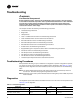
Troubleshooting
LED Operation
LED Description and Operation
There are 15 LEDs on the front of the Tracer™ UC400 controller. Figure 1, p. 14 shows the locations
of each LED and a description of its behavior in specific instances.
Marquee LED
• Shows solid green when the Tracer UC400 controller is powered and operating normally.
• Shows solid red when the Tracer UC400 controller is powered, but represents low power or
a malfunction.
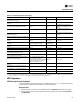
Discharge air temperature failure (ventilation
flow control with reheat)
Closed Do not care Off
Discharge air temperature failure (flow tracking
control)
Normal Do not care Do not care
Low airflow (space temperature control) Normal Normal
Local electric heat is Off; local
hydronic and all remote heat is
normal
Low airflow (ventilation flow control) Normal Do not care
Local electric heat is Off; local
hydronic is normal; remote is Don't
Care
Supply air temperature failure (space
temperature control)
Normal Normal
Local electric heat is Off
(a)
; local
hydronic and all remote heat is
normal
Supply air temperature failure (ventilation flow
control)
Normal Do not care Normal
Supply air temperature failure (flow tracking
control)
Normal Do not care Do not care
Space temperature fail (space temperature
control)
(b)
Occupied: cool minimum flow
setpoint Unoccupied: closed
Series fan enabled;
parallel fan Off
Off
Space temperature fail (ventilation flow
control)
(b)
Normal Do not care Normal
Space temperature fail (flow tracking control)
(b)
Normal Do not care Do not care
Local setpoint failure Normal Normal Normal
Flow sensor failure or flow sensor calibration
failure (space temperature control)
Normal pressure dependent control Normal Normal
Flow sensor failure or flow sensor calibration
failure (ventilation flow control)
Normal pressure dependent control Do not care Normal
Flow sensor failure or flow sensor calibration
failure (flow tracking control)
If the configured airflow tracking
offset is positive, configure
maximum airflow If the configured
airflow tracking offset is negative,
configure minimum airflow
Do not care Do not care
Freeze protection active (ventilation flow
control)
Closed Off Off
Thumbwheel in */** position (single star
position)
Minimum airflow Normal Normal
Thumbwheel in */** position (double star
position)
Maximum airflow Normal Normal
Normal Normal Normal Normal
(a) If system mode is heat or auto with a warm or hot supply air temperature
(b) When a temperature sensor fails after being valid, the controller generates a diagnostic to indicate the sensor loss condition. The controller automatically
clears the diagnostic once a valid sensor temperature value is present (non-latching diagnostic).
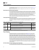
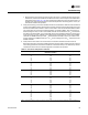
Table 10. Controller diagnostics (continued)
Diagnostic Air valve Fan Reheat