
Installation and Maintenance Manual


78 VAV-SVX07A-EN
Troubleshooting
sensor or AI5 and for supply air temperature sensor and measure the VDC. It should be
5VDC. If you have 5VDC at the Tracer™ UC400 controller the wires going to the zone have
an open. If 5VDC is not present check incoming power to the UC400 on XFMR 24 VAC input
and . Voltage should measure 24 VAC ± 10%. If you measure the proper voltage at XFMR
24 VAC input and and no voltage at AI4 and for discharge air temperature sensor or AI5
and for supply air temperature sensor. replace the Tracer UC400 controller.
CO
2
Sensor Failure Troubleshooting Procedures
WARNING
Hazardous Service Procedures!
The maintenance and troubleshooting procedures recommended in this section of the manual
could result in exposure to electrical, mechanical or other potential safety hazards. Always refer
to the safety warnings provided throughout this manual concerning these procedures. When
possible, disconnect all electrical power including remote disconnect and discharge all energy
storing devices such as capacitors before servicing. Follow proper lockout/tagout procedures to
ensure the power can not be inadvertently energized. When necessary to work with live
electrical components, have a qualified licensed electrician or other individual who has been
trained in handling live electrical components perform these tasks. Failure to follow all of the
recommended safety warnings provided, could result in death or serious injury.
In the event that the Tracer UC400 controller reports an incorrect or failed CO
2
sensor input
temperature, properly inspect the following:
1. Check that the CO
2
point is not out of service.
• Checking the config will not be necessary. The point will exist and be locked from the factory.
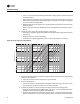
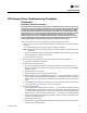
2. Check jumper position on CO
2
sensor.
• Need to be set up as 0-10VDC.
• Check voltage between UI2 and with the sensor connected.
• Should be between 1-10VDC. If it is not check incoming power.
• Check voltage input to CO
2
sensor with voltmeter.
• Needs to be between 20 to 26 VAC; nominal 24 VAC.
3. If you measure the proper voltage at incoming power and you have no VDC output at UI2 and
, replace sensor. If no voltage, check up stream of controller to see were voltage has been
interrupted. See Figure 37, p. 86 to Figure 44, p. 93 for correct unit diagrams.
Figure 36. Jumper position