Installation/ Operation Maintenance VariTrane™ Pneumatic Controls March 2002 VAV-SVX02B-EN
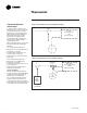
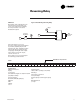
Thermostat Thermostat Selection and Location Figure 1–Two-Pipe Remote Thermostat (Reverse-Acting) In general, both one- and two-pipe thermostats have a gain of 2.5 psi per degree Fahrenheit, unless special thermostats are used that provide a different gain. The major difference between them is that a one-pipe thermostat is considered a lowcapacity thermostat and a two-pipe thermostat is considered a highcapacity thermostat.
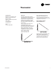
Thermostat Throttling Range: 2–10°F (1–5°C) Gain: 2.5 psi/°F Adjustable Operation Pneumatic thermostats modulate output air pressure in response to room air temperature. Pneumatic thermostats fall into two categories: directacting or reverse-acting. This section describes how thermostat output pressure responds to changes in room temperature. Figure 3 graphically illustrates the relationship between room temperature and output pressure of a direct-acting thermostat.
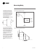
Reversing Relay Installation and Operation The reversing relay is a proportional, non-bleeding device for use in pneumatic control systems where a proportional signal from a controlling device must be reversed (see Figure 5). The most common use of the reversing relay is to change the action of a pneumatic thermostat. Figure 5–Pneumatic Reversing Relay Trane Part No. RLY-755 Figure 6–Reversing Relay Connections Output Branch S 20 (137.9) 9 PSI In (62.06 kPa) B Reversing Relay M 9 PSI Out (62.
Reversing Relay Figure 8–Recalibrating Reversing Relay Calibration By using the “bias” adjustment on the relay, the factory-set 8.0–9.0 “crossover” can be changed. To recalibrate, the relay should be connected as illustrated in Figure 8. Gage 1 Pressure Regulator Bias Adjustment Screw C M 3 M If the new desired “cross-over” pressure is 11.0 psi, this must be applied to port #3 by adjusting the pressure regulator. The “bias” adjustment is then turned until 11.0 psi is obtained on the output gage.
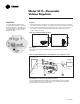
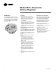
Model 3011—Pneumatic Volume Regulator Model 3011 The model 3011 Pneumatic Volume Regulator (PVR) is capable of operating with normally-open or normally-closed air valves and can operate with either direct-acting (DA) or reverse-acting (RA) thermostats. Installation 1. Attach bracket either vertically or horizontally to the illustration surface. Horizontal is preferred, vertical is acceptable, any other position is not acceptable (see Figure 9). 2. Insert controller into its bracket.
Model 3011—Pneumatic Volume Regulator Use the following procedure to set-up the PVR: 1. Select damper action (NO or NC). Loosen damper selection switch screw and align to either the NO or NC pointer with damper pointer and tighten screw. 2. Now determine the type of thermostat that will be used. If a direct-acting thermostat is used, the reset start pressure is typically 8 psi. If a reverse-acting thermostat is used, the reset start pressure is typically 3 psi (see Figure 11). 3.
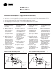
Calibration Procedures Calibration Procedure (Steps 1–4 apply to all thermostat models) 1. Be sure the PVR is installed correctly and that all connections are hooked up to the proper ports. See Figure 9 for unit application. 2. Remove the caps on the tees which are connected to the lines to the flow sensor. Connect a 0–2" magnehelic gage to monitor flow sensor delta P. The higher-pressure port is further upstream on the air valve inlet. 3.
Specifications (3011) Specifications (3011) Differential Pressure Range: 0 to 1.0 in. wg Minimum Setpoint Range: 0 to 1.0" H2O Maximum Setpoint Range: minimum to 1.0 in. wg Operating Static Range: 0.25–6.0 in. wg Normal Supply Air Pressure: 20.0 psi Reset Span Range: 0–10 psi Minimum Supply air Pressure: 15.0 psi Maximum Safe Thermostat Input: 30 psi (closed chamber) Maximum Supply Air Pressure: 30.0 psi Operating Temperature: +40/+120°F Average Supply Air Consumption: 28.
Model 3501—Pneumatic Volume Regulator Model 3501 The model 3501 Pneumatic Volume Regulator (PVR) is capable of operating with normally-open or normally-closed air valves and can operate with either direct-acting (DA) or reverse-acting (RA) thermostats. Installation 1. Attach bracket either vertically or horizontally to the installation surface. Horizontal is preferred, vertical is acceptable, any other position is not acceptable. 2. Insert controller into its bracket.
Calibration Procedures Calibration Procedure (Steps 1–4 apply to all thermostat models) 1. Be sure the PVR is installed correctly and that all connections are hooked up to the proper ports. 2. Remove the caps on the tees, which are connected to the lines to the flow sensor. Connect a 0–2" magnehelic gage to monitor flow sensor delta P. The higher-pressure port is further upstream on the air valve inlet. 3. Remove the thermostat line and connect a hand pump with a 0–20 psi gage to port “T“. 4.
Specifications (3501) Specifications (3501) Differential Pressure Range: 0 to 1.0 in. wg Minimum Setpoint Range: 0 to 1.0" H2O Maximum Setpoint Range: minimum to 1.0 in. wg Maximum Setpoint Range: 6.0 in. wg Normal Supply Air Pressure: 20.0 psi Minimum Supply air Pressure: 15.0 psi Output Sensitivity: 5 psi/.02 Average Supply Air Consumption: 43.
MCP-3631—Rotary Pneumatic Damper Actuator MCP-3631—Rotary Pneumatic Damper Actuator Description: Rotary actuators mounts to a standard ½" diameter shaft by a locking collar and bushing. Models: MCP-3631-5000 8–13 psi range (55–90 kPa) Normally-Closed operation MCP-3631-8000 3–8 psi range (21–55 kPa) Normally-Open operation Installation Method: Slide collar onto shaft. Slide actuator onto shaft noting directional rotation.
Constant-Volume Dual-Duct Calibration (3011) Constant Volume Dual-Duct Calibration (3011) This calibration procedure is used when a constant volume of air must be maintained through a unit. On a dualduct unit, a constant-volume discharge sensor is used to measure the air leaving the unit. The PVR controlling to a constant-volume of air leaving the unit uses the discharge sensor to maintain the specified cfm. This PVR does not require a thermostat connected to the PVR.
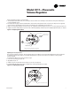
Variable Air Volume Dual-Duct Calibration (3011) Variable-Air-Volume DualDuct Calibration (3011) Figure 16–Typical VAV Dual-Duct Piping Diagram Figure 16 is a typical piping diagram of a VAV dual-duct unit. The unit has a thermostat piped to both pneumatic volume regulators (PVR) which will operate the heating deck from a thermostat signal of 3–8 psi. The cooling deck will operate from a thermostat signal of 8–13 psi.
Constant-Volume Single-Duct VAV (VCV 3011) Constant-Volume SingleDuct VAV ( VCV 3011) This is used when a constant volume of air is required to supply a zone. A thermostat is still often required to modulate a reheat coil to maintain temperature control. The thermostat is never connected to the “T” port on the volume regulator. The following procedure is used to calibrate this type of unit with a PVR. 1. Be sure there is 0 psi at the “T” port. 2. Set LO thermostat adjustment knob to desired unit cfm.