
User manual


86 RT-PRC005-EN
Mechanical
Specifications
Controls
Unit shall be completely factory-wired
with necessary controls and contactor
pressure lugs or terminal block for power
wiring. Unit shall provide an external
location for mounting a fused disconnect
device.
A choice of microprocessor or
electromechanical controls shall be
available.
Microprocessor controls provide for all 24
volt control functions. The resident control
algorithms shall make all heating, cooling,
and/or ventilating decisions in response
to electronic signals from sensors
measuring indoor and outdoor
temperatures. The control algorithm
maintains accurate temperature control,
minimizes drift from set point, and
provides better building comfort. A
centralized Microprocessor shall provide
anti-short cycle timing and time delay
between compressors to provide a
higher level of machine protection.
24-volt electromechanical control circuit
shall include control transformer and
contactor pressure lugs for power wiring.
Units shall have single point power entry
as standard.
Accessories/Options
Electric Heaters
Factory or field-installed electric heat
modules shall be available for installation
within basic unit. Electric heater elements
shall be constructed of heavy-duty nickel
chromium elements internally delta
connected for 240 volt, wye connected
for 480 and 600 volt. Staging shall be
achieved through the unitary control
processor (UCP). Each heater package
shall have automatically reset high limit
control operating through heating
element contactors. All heaters shall be
individually fused from the factory, where
required, and shall meet all NEC and CEC
requirements when properly installed.
Power assemblies shall provide single-
point connection. Electric heat modules
shall be UL listed or CSA certified.
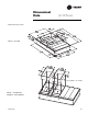
Roof Curb
The roof curb shall be designed to mate
with the unit’s downflow supply and
return and provide support and a water
tight installation when installed properly.
The roof curb design shall allow field-
fabricated rectangular supply/return
ductwork to be connected directly to the
curb. Curb design shall comply with
NRCA requirements. Curb shall be
shipped knocked down for field assembly
and shall include wood nailer strips.
Economizer
This accessory shall be either field or
factory-installed and shall be available
with or without barometric relief. The
assembly includes fully modulating 0-100
percent motor and dampers, minimum
position setting, preset linkage, wiring
harness with plug, spring return actuator
and fixed dry bulb control. The barometric
relief shall provide a pressure operated
damper that shall be gravity closing and
shall prohibit entrance of outside air
during the equipment “off” cycle.
Optional solid state or differential
enthalpy control shall be available for
either factory or field installation. The
factory-installed economizer arrives in
the shipping position and shall be moved
to the operating position by the installing
contractor.
Powered Exhaust
The field installed powered exhaust,
available for 6-10 ton units, shall provide
exhaust of return air, when using an
economizer, to maintain better bulding
pressurization.
Remote Potentiometer
The minimum position setting of the
economizer shall be adjusted with this
accessory.
Manual Outside Air Damper
Factory or field-installed rain hood and
screen shall provide up to 50 percent
outside air.
Motorized Outside Air Dampers
Factory or field-installed manually set
outdoor air dampers shall provide up to
50 percent outside air. Once set, outdoor
air dampers shall open to set position
when indoor fan starts. The damper shall
close to the full closed position when
indoor fan shuts down.