Architectural Hydronic Wall Fin October 2001 FIN-PRC004-EN
Features and Benefits A Complete Line of Wall Fin Trane architectural wall fin is ideal for heating modern commercial, institutional or industrial buildings. Attractive styling and wide application flexibility allow wall fin cabinet designs to be used for virtually any application. Available for hydronic or steam heating, Trane wall fin can also be used in combination with convectors for smaller areas, allowing for the use of one source when designing a radiation heating system.
Contents Architecural Wall Fin Features and Benefits 2 Application Considerations 6 Selection Procedure 7 Performance Data 14 Dimensional Data 41 Options 54 Mechanical Specifications 56 Security Wall Fin Features and Benefits 74 Accessories 75 Model Number Description 76 Performance and General Data 77 Dimensional Data 85 Mechanical Specifications 91 Hydronic Light Commercial Slope Top Wall Fin — Model 11S FIN-PRC004-EN Features and Benefits 93 Performance and General Data 96
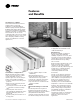
Features and Benefits A simple installation designed to last without visible fasteners — Trane’s exclusively designed mounting strip makes it possible. Cabinet enclosures and accessory panels hinge-lock easily into mounting strip. Serves as plaster Curved rectangular stop for semimetal washers to recessed assure tight fit against installations. the wall. Mounting strip keys entire Serves as wall installation, attaches to any panel stop.
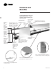
Features and Benefits Positive Temperature Control Hydronic Heating Elements — Copper/ Aluminum and Steel Copper-Aluminum Elements 3 /4”, 1” and 1 1/4” (19 mm, 25 mm and 32 mm) Copper Tubes With 40, 50 or 58 Aluminum Fins per foot (131, 164 190 per meter). • Efficient element-mounted damper. • Reduces unit capacity by 70 percent. • Has jam-proof bead chain control system. • Control knob is mounted on the outlet grille.
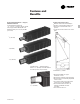
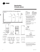
Application Considerations A Heating System and Style to Suit Any Application Type E Type X Wall Mounted F Front Outlet S Slope Top Outlet T Top Outlet TA Enclosure styles meet the heating needs of long, open areas in any interior. • Wall-mounted wall fin enclosures available in depths of four and six inches (102 mm, 152 mm). • Enclosure depth is determined by the type of element to be used. • See pages 13 through 43 and Tables PD-1 through PD-25 for details. • Front inlet grilles.
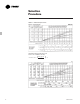
Selection Procedure Hydronic/Steam Wall Fin Selection Hot Water Systems The capacity rating of wall fin in a hot water heating system depends on the difference between average water temperature and entering air temperature, and on the velocity at which water is circulated through the tube. The effect of water velocity on the capacity rating is appreciable (see Chart S-1) and should be taken into account when selecting wall fin. Following are example selections for hot water systems.
Selection Procedure Chart S-1 — Water Velocity Correction Factors — Pressure Drops ENGLISH All Catalog Capacities Based On 3.0 Feet Per Second Water Velocity.* *Correction Factor = ( Water Velocity 3 ) .
Selection Procedure Effect of Temperature Drop On Fin-Tube Ratings The effect of temperature drop on heat output of a wall fin element can be readily determined.
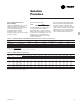
Selection Procedure Table S-3 — Correction Factors for Non-Standard Average Water Temperatures Average Water Temp. (F) (C) 170 77 180 82 190 88 200 93 210 99 220 104 230 110 240 116 250 121 260 127 270 132 280 138 290 143 300 149 45°F 7°C .82 .91 1.00 1.09 1.18 1.27 1.37 1.47 1.57 1.67 1.78 1.88 1.98 2.08 50°F 10°C .77 .86 .94 1.03 1.12 1.21 1.30 1.41 1.50 1.60 1.70 1.80 1.90 2.00 55°F 13°C .72 .81 .89 .97 1.06 1.15 1.24 1.35 1.44 1.52 1.62 1.72 1.82 1.
Selection Procedure Rating Adjustment for Greater Than Cataloged Installed Height-Heating Effect Ratings in Tables PD-1 through PD-25 include the factor shown in Table S-5 for installed heights recommended. Installed height defines the installed location that is the basis for the published rating and determines the percentage which may be added to condensation capacity.
Selection Procedure Maximum Installed Lengths Hot water systems velocity and pressure drop are two factors that will influence the maximum installed lengths of wall fin hot water systems. Velocity in any pipe size is dependent upon the capacity of the installed wall fin and the water temperature drop through the unit. Table S-6 gives the maximum installed capacity for any single wall fin unit or loop based on *5 ft./sec (1.5 m/sec).
Selection Procedure Provisions For Expansion Copper tube wall fin elements and copper tubing, when installed at 40°F (4.4°C) and operated at 200°F (93°C) average water temperature, will expand as much as 1/8” (3.2 mm) in each 10’ (3 m) length. Provisions must be made to accommodate this expansion at the heating element supports and at the ends of the wall fin elements and piping.
Performance Data Bare Element Capacities Table PD-1 — Ratings of Wall Fin Copper/Aluminum Elements Without Enclosures Steam Capacity Per Ft.-1 Psi at 65°F Air Per Meter - 6.895 kPa at 18.3°C Air Element Fin Series Per Foot Per Meter Tiers 1 2* 3 /4” CA 19 mm Copper Tube Alum. Fins Fins 3 1/4 “ x 3 1/4” 83 x 83 mm Thickness .0135” .34 mm 40 131m 2** 3** 1† 1 2* 50 164 m 2** 3** 1† 1 2* 58 190 m 2** 3** 1† 14 Install.
Performance Data Table PD-1 — Ratings of Wall Fin Copper/Aluminum Elements Without Enclosures Steam Capacity Per Ft.-1 Psi at 65°F Air Per Meter - 6.895 kPa at 18.3C Air Element Fin Series Per Foot Per Meter Tiers 1 2* 1” CA 25 mm Copper Tube Alum. Fins Fins 3 1/4” x 3 1/4” 83 x 83 mm Thickness .0135” .34 mm 40 131m 2** 3** 1† 1 2* 50 164 m 2** 3** 1† 1 2* 58 190 m 2** 3** 1† Install.
Performance Data Table PD-2 — Ratings of Wall Fin Copper/Aluminum Elements Without Enclosures Steam Capacity Per Ft.-1 Psi at 65°F Air Per Meter - 6.895 kPa at 18.3C Air Element Fin Series Per Foot Per Meter Tiers 1 2* 1 1/4” CA 32 mm Copper Tube Alum. Fins Fins 3 1/4” x 3 1/4” 83 x 83 mm Thickness .0135” .34 mm 40 131 m 2** 3** 1† 1 2* 50 164 m 2** 3** 1† 1 58 190 m 2* 2** 3** 1† 16 Install.
Performance Data Table PD-2 — Ratings of Wall Fin Copper/Aluminum Elements Without Enclosures Steam Capacity Per Ft.-1 Psi at 65°F Air Per Meter - 6.895 kPa at 18.3C Air Element Fin Series Per Foot Per Meter Tiers 1 2* 1 1/4” CA 32 mm Copper Tube Alum. Fins Fins 3 1/4” x 5 1/4” 83 x 133 mm Thickness .0135” .34 mm 40 131 m 2** 3** 1† 1 2* 50 164 m 2** 3** 1† 1 2* 58 190 m 2** 3** 1† Install.
Performance Data Table PD-3 — Ratings of Wall Fin Steel Elements Without Enclosures Steam Capacity Per Ft.-1 Psi at 65°F Air Per Meter - 6.895 kPa at 18.3°C Air Element 1 1/4” Steel 32 mm Steel Tube Steel Fins Fins 2 1/2” x 5 1/4” 64 x 133 mm Thickness .027” .69 mm Fin Series Per Foot Per Meter Tiers 1 2* 52 171m 2** 3** 1† Install. Height Inches mm 9 229 13 330 17 432 23 584 — Hot Water Capacity Btu/Hr./Ft. — At 65°F Air, Average Water Temperature Watts/Meter — At 18.
Performance Data Sloping Top Table PD-4 — Ratings 4” (102 mm) Deep, Type S - Enclosure With Copper/Aluminum Elements Steam Capacity Per Ft.-1 Psi at 65°F Air Per Meter - 6.895 kPa at 18.3°C Air Element Fin Series Per Foot Per Meter Tiers Encl. 10S 14S 1 18S 24S 3 /4” CA 19 mm Copper Tube Alum. Fins Fins 3 1/4” x 3 1/4” 83 x 83 mm Thickness .0135” .
Performance Data Sloping Top Table PD-5 — Ratings 4” (102 mm) Deep, Type S - Enclosure With Copper/Aluminum Elements Steam Capacity Per Ft.-1 Psi at 65°F Air Per Meter - 6.895 kPa at 18.3°C Air Element Fin Series Per Foot Per Meter Tiers Encl. 10S 14S 1 18S 24S 1” CA 25 mm Copper Tube Alum. Fins Fins 3 1/4” x 3 1/4” 83 x 83 mm Thickness .0135” .34 mm 40 131 m 2* 14S 18S 2** 24S 10S 14S 1 18S 24S 50 164 m 2* 14S 18S 2** 24S 10S 14S 1 18S 24S 58 190 m 2* 14S 18S 2** 24S Install.
Performance Data Sloping Top Table PD-6 — Ratings 4” (102 mm) Deep, Type S - Enclosure With Copper/Aluminum Elements Steam Capacity Per Ft.-1 Psi at 65°F Air Per Meter - 6.895 kPa at 18.3°C Air Element Fin Series Per Foot Per Meter Tiers Encl. 10S 14S 1 18S 24S 1 1/4” CA 32 mm Copper Tube Alum. Fins Fins 3 1/4” x 3 1/4” 83 x 83 mm Thickness .0135” .
Performance Data Sloping Top Table PD-7 — Ratings 6” (152 mm) Deep, Type S - Enclosure With Copper/Aluminum Elements Steam Capacity Per Ft.-1 Psi at 65°F Air Per Meter - 6.895 kPa at 18.3°C Air Element Fin Series Per Foot Per Meter Tiers Encl. 12S 16S 1 20S 24S 1 1/4” CA 32 mm Copper Tube Alum. Fins Fins 3 1/4” x 5 1/4” 83 x 133 mm Thickness .0135” .
Performance Data Sloping Top Table PD-8 — Ratings 6” (152 mm) Deep, Type S - Enclosure With Steel Elements Steam Capacity Per Ft.-1 Psi at 65°F Air Per Meter - 6.895 kPa at 18.3°C Air Element Fin Series Per Foot Per Meter Tiers Encl. 12S 16S 1 1/4” Steel 32 mm Steel Tube Steel Fins Fins 2 1/2” x 5 1/4” 64 x 133 mm Thickness .027” .69 mm 1 20S 24S 52 171 m 16S 2* 20S 24S 20S 2** 24S Install.
Performance Data Front Outlet Table PD-9 — Ratings 4” (102 mm) Deep, Type F - Enclosure With Copper/Aluminum Elements Steam Capacity Per Ft.-1 Psi at 65°F Air Per Meter - 6.895 kPA at 18.3°C Air Element Fin Series Per Foot Per Meter Tiers Encl. 10F 14F 1 18F 24F 3 /4” CA 19 mm Copper Tube Alum. Fins Fins 3 1/4” x 3 1/4” 83 x 83 mm Thickness .0135” .
Performance Data Front Outlet Table PD-10 — Ratings 4” (102 mm) Deep, Type F - Enclosure With Copper/Aluminum Elements Steam Capacity Per Ft.-1 Psi at 65°F Air Per Meter - 6.895 kPa at 18.3°C Air Element Fin Series Per Foot Per Meter Tiers Encl. 10F 14F 1 18F 24F 1” CA 25 mm Copper Tube Alum. Fins Fins 3 1/4” x 3 1/4” 83 x 83 mm Thickness .0135” .34 mm 40 131 m 2* 14F 18F 2** 24F 10F 14F 1 18F 24F 50 164 m 2* 14F 18F 2** 24F 10F 14F 1 18F 24F 58 190 m 2* 14F 18F 2** 24F Install.
Performance Data Front Outlet Table PD-11 — Ratings 4” (102 mm) Deep, Type F - Enclosure With Copper/Aluminum Elements Steam Capacity Per Ft.-1 Psi at 65°F Air Per Meter - 6.85 kPa at 18.3°C Air Element Fin Series Per Foot Per Meter Tiers Encl. 10F 14F 1 18F 24F 1 1 /4” CA 32 mm Copper Tube Alum. Fins Fins 3 1/4” x 3 1/4” 83 x 83 mm Thickness .0135” .
Performance Data Front Outlet Table PD-12 — Ratings 6” (152 mm) Deep, Type F - Enclosures With Copper/Aluminum Elements Steam Capacity Per Ft.-1 Psi at 65°F Air Per Meter - 6.895 kPa at 18.3°C Air Element Fin Series Per Foot Per Meter Tiers Encl. 12F 16F 1 20F 24F 1 1/4” CA 32 mm Copper Tube Alum. Fins Fins 3 1/4” x 5 1/4” 83 x 133 mm Thickness .0135” .
Performance Data Front Outlet Table PD-13 — Ratings 6” (152 mm) Deep, Type F - Enclosures With Steel Elements Steam Capacity Per Ft.-1 Psi at 65°F Air Per Meter - 6.895 kPa at 18.3°C Air Element Fin Series Per Foot Per Meter Tiers Encl. 12F 16F 1 1/4” Steel 32 mm Steel Tube Steel Fins Fins 1 1/2” x 5 1/4” 64 x 133 mm Thickness .027” .69 mm 1 20F 24F 52 171 m 16F 2* 20F 24F 20F 2** 24F Install.
Performance Data Top Outlet Table PD-14 — Ratings 4” (102 mm) Deep, Type T - Enclosures With Copper/Aluminum Elements Steam Capacity Per Ft.-1 Psi at 65°F Air Per Meter - 6.895 kPa at 18.3°C Air Element Fin Series Per Foot Per Meter Tiers Encl. 10T 14T 1 18T 24T 3 /4” CA 19 mm Copper Tube Alum. Fins Fins 3 1/4” x 3 1/4” 83 x 83 mm Thickness .0135” .
Performance Data Top Outlet Table PD-15 — Ratings 4” (102 mm) Deep, Type T - Enclosures With Copper/Aluminum Elements Steam Capacity Per Ft.-1 Psi at 65°F Air Per Meter - 6.895 kPa at 18.3°C Air Element Fin Series Per Foot Per Meter Tiers Encl. 10T 14T 1 18T 24T 1” CA 25 mm Cooper Tube Alum. Fins Fins 3 1/4” x 3 1/4” 83 x 83 mm Thickness .0135” .34 mm 40 131m 2* 14T 18T 2** 24T 10T 14T 1 18T 24T 50 164 m 2* 14T 18T 2** 24T 10T 1 14T 18T 24T 58 190 m 2* 14T 18T 2** 24T Install.
Performance Data Top Outlet Table PD-16 — Ratings 4” (102 mm) Deep, Type T - Enclosures With Copper/Aluminum Elements Steam Capacity Per Ft.-1 Psi at 65°F Air Per Meter - 6.895 kPa at 18.3°C Air Element Fin Series Per Foot Per Meter Tiers Encl. 10T 14T 1 18T 24T 1 1/4” CA 32 mm Copper Tube Alum. Fins Fins 3 1/4” x 3 1/4” 83 x 83 mm Thickness .0135” .
Performance Data Top Outlet Table PD-17 — Ratings 6” (152 mm) Deep, Type T - Enclosures With Copper/Aluminum Elements Steam Capacity Per Ft.-1 Psi at 65°F Air Per Meter - 6.895 kPa at 18.3°C Air Element Fin Series Per Foot Per Meter Tiers Encl. 12T 16T 1 20T 24T 1 1/4” CA 32 mm Copper Tube Alum. Fins Fins 3 1/4” x 5 1/4” 83 x 133 mm Thickness .0135” .
Performance Data Top Outlet Table PD-18 — Ratings 6” (152 mm) Deep, Type T - Enclosures With Steel Elements Steam Capacity Per Ft.-1 Psi at 65°F Air Per Meter - 6.895 kPa at 18.3°C Air Element Fin Series Per Foot Per Meter Tiers Encl. 12T 16T 1 1/4” Steel 32 mm Steel Tube Steel Fins Fins 2 1/2” x 5 1/4” 65 x 133 mm Thickness .027” .69 mm 1 20T 24T 52 171 m 16T 2* 20T 24T 20T 2* 24T Install.
Performance Data Top Outlet – TA Table PD-19 — Ratings 4” (102 mm) Deep, Type TA - Enclosures With Copper/Aluminum Elements Steam Capacity Per Ft.-1 Psi at 65°F Air Per Meter - 6.895 kPa at 18.3°C Air Element Fin Series Per Foot Per Meter Tiers Encl. 10TA 14TA 1 18TA 24TA 3 /4” CA 19 mm Copper Tube Alum. Fins Fins 3 1/4” x 3 1/4” 83 x 83 mm Thickness .0135” .
Performance Data Top Outlet – TA Table PD-20 — Ratings 4” (102 mm) Deep, Type TA - Enclosures With Copper/Aluminum Element Steam Capacity Per Ft.-1 Psi at 65°F Air Per Meter - 6.895 kPa at 18.3°C air Element Fin Series Per Foot Per Meter Tiers Encl. 10TA 14TA 1 18 TA 24TA 1” CA 25 mm Copper Tube Alum. Fins Fins 3 1/4” x 3 1/4” 83 x 83 mm Thickness .0135” .
Performance Data Top Outlet – TA Table PD-21 — Ratings 4” (102 mm) Deep, Type TA - Enclosures With Copper/Aluminum Elements Steam Capacity Per Ft.-1 Psi at 65°F Air Per Meter - 6.895 kPa at 18.3°C Air Element Fin Series Per Foot Per Meter Tiers Encl. 10TA 14TA 1 18TA 24TA 1 1 /4” CA 32 mm Copper Tube Alum. Fins Fins 3 1/4” x 3 1/4” 83 x 83 mm Thickness .0135” .
Performance Data Top Outlet – TA Table PD-22 — Ratings 6” (152 mm) Deep, Type TA - Enclosures With Copper/Aluminum Elements Steam Capacity Per Ft.-1 Psi at 65°F Air Per Meter - 6.895 kPa at 18.3°C Air Element Fin Series Per Foot Per Meter Tiers Encl. 12TA 16TA 1 20TA 24TA 1 1 /4” CA 32 mm Copper Tube Alum. Fins Fins 3 1/4” x 5 1/4” 83 x 133 mm Thickness .0135” .
Performance Data Top Outlet – TA Table PD-23 — Ratings 6” (152 mm) Deep, Type TA - Enclosures With Steel Elements Steam Capacity Per Ft.-1 Psi at 65°F Air Per Meter - 6.895 kPa at 18.3°C Air Element Fin Series Per Foot Per Meter Tiers Encl. 12TA 16TA 1 1/4” Steel 32 mm Steel Tube Steel Fins Fins 2 1/2” x 5 1/4” 64 x 133 mm Thickness .027” .69 mm 1 20TA 24TA 52 171 m 16TA 2* 20TA 24TA 20TA 2* 24TA Install.
Performance Data Table PD-24 — Ratings, Type 3E and E3 Enclosures With Copper/Aluminum Elements Steam Capacity Per Ft.-1 Psi at 65°F Air Per Meter - 6.89 kPa at 18.3°C Air Element 3 /4” CA 19 mm Copper Tube Alum. Fins Fins 3 1/4” x 3 1/4” 83 x 83 mm Thickness .0135” .34 mm Fin Series Per Foot Per Meter 40 131 m Tiers Encl. 3E 1 E3* 3E 50 164 m 1 E3* 3E 58 190 m 1” CA 25 mm Copper Tube Alum. Fins Fins 3 1/4” x 3 1/4” 83 x 83 mm Thickness .0135” .
Performance Data Table PD-25 — Ratings, Type 4E, E3 and E3-2W Enclosures With Copper/Aluminum Elements Steam Capacity Per Ft.-1 Psi at 65°F Air Per Meter - 6.895 kPa at 18.3°C Air Element 1 1/4” CA 32 mm Copper Tube Alum. Fins Fins 3 1/4” x 5 1/4” 83 x 133 mm Thickness .015” .38 mm Fin Series Per Foot Per Meter 40 131 m 50 164 m 58 190 m 1 1/4” Steel 32 mm Steel Tube Steel Fins Fins 2 1/2” x 5 1/4” 64 x 133 mm Thickness .027” .69 mm 52 171 m Install. Height Inches Tiers Encl.
Dimensional Data Element Location For Hot Water Systems Sloping Top Sloping Top Type S 1” (25) 1 3/8 (35) 2 3/4 (70) D A E 3 3/4 (95) C 2 Or 3 (51 or 76) B Dimensions shown in ( ) are in millimeters. Table DD-1 — Type S — Enclosure Dimensions Enclosure Depth Fin Size Tube Size A B C Min. Max. D E Min. Max. F 3 10” (254) 4” (102) 2 1/4” (57) 4 1/4” (108) 2 1/4” (57) — — — — 4 7/8” (124) /4” (19) Cu.
Dimensional Data Element Location For Hot Water Systems Front Outlet Type F Front Outlet 1” (25) 1 3/8 (35) 2 3/4 (70) D A E 3 3/4 (95) C 2 Or 3 (51 Or 76) B Dimensions shown in ( ) are in millimeters. Table DD-2 — Type F — Enclosure Dimensions Enclosure Depth Fin Size Tube Size A B C Min. Max. D E Min. Max. F 3 10” (254) 4” (102) 2 1/4” (57) 4 1/4” (108) 2 1/4” (57) — — — — 4 7/8” (124) /4” (19) Cu.
Element Location For Hot Water Systems Dimensional Data Top Outlet Top Outlet Type T — 4” Deep (Flat Top) Top Outlet Type T — 6” Deep (Recessed Grille) 1” (25) 1” (25) 1 3/8 (35) 3 1 /8 (35) D 2 3/4 (70) 3 /8 (10) 2 3/4 (70) F A F A E 3 3/4 (95) C E 2 (51) 3 3/4 (95) C B 3 (76) B Dimensions shown in ( ) are in millimeters. Table DD-3 — Type T — Enclosure Dimensions Enclosure Depth Fin Size Tube Size A B C Min. Max. D E Min. Max.
Dimensional Data Element Location For Hot Water Systems Top Outlet – TA Top Outlet Extruded Grille Type TA 1” (25) 3 1 /8 (35) D 2 3/4 (70) F A E 3 3/4 (95) C 2 Or 3 (51 or 76) B Dimensions shown in ( ) are in millimeters. Table DD-4 — Type TA — Enclosure Dimensions Enclosure Depth Fin Size Tube Size A B C Min. Max. D E Min. Max. F 3 10” (254) 4” (102) 2 1/4” (57) 4 1/4” (108) 2 1/4” (57) — — — — 4 7/8” (124) /4” (19) Cu.
Dimensional Data Type — E, E3 And E3-2W Dimensions Wall Mounted Table DD-5 — Enclosure Dimensions, Type E Enclosure Type Wall Mounted Fin Size Tube Size A B C D E 3 /4” (19) Cu. 5 1/8” (130) 4” (102) 2 3/8” (60) 2” (51) 3 1/4” (83) 3E 3 1/4” x 3 1/4” (83 x 83) Alum. 1” (25) Cu. 5 1/8” (130) 4” (102) 2 1/2” (64) 2” (51) 3 1/4” (83) 1 1/4” (32) Cu. 5 1/8” (130) 4” (102) 2 5/8” (67) 2” (51) 3 1/4” (83) 4E 3 1/4” x 5 1/4” 2 1/2” x 5 1/4” (83 x 133) Alum. (64 x 133) Steel 1 1/4” (32) Cu.
Dimensional Data Bottom Air Inlet Grille Type T — 4” Deep x 14” High Top Outlet Enclosure with Bottom Inlet Grille shown. Type T — 6” Deep x 16” High Top Outlet Enclosure with Bottom Inlet Grille shown. 1. Heating Element with 3 1/4” x 3 1/4” size fins. 2. Front Panel with stamped sheet metal Bottom Air Inlet Grille. 3. Mounting Strip. 4. Mounting Strip Support Washer. 5. Type 4X Wall Bracket. 6. Element Cradle. 7. Mounting Fasteners by others. 1. Heating Element with 3 1/4” x 5 1/4” size fins. 2.
Dimensional Data 10PE Pipe Enclosures 12PE 14PE 1. Enclosure 2. Mounting Strip 3. Mounting Washer 4.
Dimensional Data 16PE Pipe Enclosures 18PE 20PE 1. Enclosure 2. Mounting Strip 3. Mounting Washer 4.
Dimensional Data 24PE Pipe Enclosures 24PE 1. Enclosure 2. Mounting Strip 3. Mounting Washer 4.
Dimensional Data Element, Enclosure And Cover Length — General The over-all length of an enclosure or cover, or of several joined together, is the same as the ordering length. Over- all length when an end panel is used is 1” (25 mm) longer than the ordering length. Over-all length when right and left end panels are used is 2” (51 mm) longer than the ordering length. For wall-to-wall installations, use total length to the nearest 6” (152 mm) increment below the actual wall-to-wall measurement.
Dimensional Data Standard Cabinet And Element Mounting Locations Figure DD-1 — Element and Pipe Support Spacing Figure DD-2 — 4” (102 mm) Deep Enclosures Note: Extra clusters of slots provided in 22-inch (559 mm) high bracket, for additional element/pipe supports. 24” (610) 22” (559) 1 3/4” (44) 10” (254) 22” (559) FOR 6” (152) DEEP UNITS 18” (457) FOR 4” (102) DEEP UNITS 2” (51) Min. 5” (127) Max. 1 5/8” (41) Min. 4 5/8” (118) Max.
Dimensional Data Element Dimensions – Table DD-7 Ordering Length A B 2 1/2” (64) Finned Length 1 7/8” (48) 1 1/4” (32) Copper-Aluminum Ordering Length A Ordering Length A B B Finned Length 2 1/2” (64) 1 1/4” (32) Steel-Threaded Finned Length 2 1/2” (64) 2 1/2” (64) 1 1/4” (32) Steel-Chamfered TYPE X ENCLOSURE Type X Enclosure — One Row of Element, Wall Mounted – Table DD-8 B A TYPE X ENCLOSURE WALL HANGER AND CEILING HANGER Type X enclosure ratings are 3 percent less than bare element ratin
Dimensional Data Table DD-7 — Wall Fin Element Dimensions 3 /4” (19) , 1” (25 mm) Or 1 1/4” (32) Copper Aluminum Series 40-50-58 3 1/4” (83) 3 1/4” (83) Dimension A B 1 1/4” (32) Copper Aluminum Series 40-50-58 5 1/4” (133) 3 1/4” (83) 1 1/4” (32) Steel Series 52 5 1/4” (133) 2 1/2” (64) Table DD-8 Enclosure Type 4x 3 1/4” (83) Fin 4 5/8” (117) 4” (102) 3 ¼” (83) Dimension A B E 5x 5 1/4” (133) Fin 4 5/8” (117) 6” (152) 3 ¼” (83) Table DD-9 Enclosure Type 10x Dimension A B C D E 12x 3 1/4” (83) F
Options Type T — Top Outlet Wall Fin Enclosure Shown 5” (127) 2” (51 mm) 2” (51 mm) Dirt Guard Gasket Fastens to back of the mounting strip to prevent wall streaking. Enclosure Extensions Enclosure extensions are designed to provide additional length to standard enclosures on wall-to-wall installations or when additional length is required to fully cover elements and piping. Outside Corner Special Purpose Accessories These accessories can be used with Type S, F, T and TA enclosures.
Options 6” (152) Or 12” (305) 12” (305) 5” (127) x 6” (152) ACCESS DOOR Access Panel with Access Door 12” (305) long with a 5” (127) x 6” (152) access door to gain access to valves. Access Panel To gain access inside the Wall Fin enclosure to valves.
Mechanical Specifications General The contractor shall furnish and install Trane wall fin as shown on the plans. Ratings shall be IBR approved. Units shall be installed in a neat and workmanlike manner in accordance with specifications and manufacturer recommendations. Type 3E and 4E enclosures shall be 16gauge (1.5 mm thickness) or 14-gauge (1.9 mm thickness) steel. Type E3 and E32W enclosures shall be 16-gauge steel.
Mechanical Specifications Type E3A-1W and E3A-2W with Aluminum Air Outlet Grilles Specifications Natural convection with extruded aluminum air out grille(s). Pedestal floor mounted wall fin shall be furnished to meet the specified capacity. Enclosures etc., heating elements and accessories shall be installed in accordance with the manufacture’s recommendations.
Mechanical Specifications Color Finish All enclosures, back plate/mounting strip and accessories shall be painted with a baked-on commercial primer paint as standard. Optional baked-on enamel color finishes shall be available. Color Options Baked-on enamel color finish shall be chosen from Color Selection Chart UNT-S-10 May 1994.
Mechanical Specifications Model E3A-1W Model E3A-2W FIN-PRC004-EN 59
Mechanical Specifications Installation Layout for Pedestal Mount E3A-1W One Wide Enclosure 3” (76 mm) End Assembly Wall Sleeve Support (Slotted For Piping Where Specified) Wall Sleeve 4” (102 mm) or 8 3/8” (213 mm) (Access Door Optional 8 3/8” (213 mm) Only) Enclosure Assembly — Typical Wall Sleeve in Run At Each Joint Corner — Inside and/or Outside Short Leg Dimension 8 3/8” (213 mm) Cradle Pedestal Bracket Assembly Note: Fasten accessory with 6 S.M. Screw through solid part of grille.
Mechanical Specifications Metric Conversions 1 Psi = 6.895 kPa (Kilo Pascals) at 65°F Air = 18.3°C Air Sq. Ft. EDR at 1 Psi (6.895 kPa) at 65°F Air (18.3°C) Air x 240 BTU = Total BTU’s (Watts) 1 BTU/HR. = 0.2931 Watts 1 Foot = 0.3048 Meters - 1 Meter = 3.2808 Feet 1 BTU/HR/FT = 0.9616 Watts/Meter 10.7639 Sq. Feet = 1 Square Meter 1 Lbs = 0.4536 Kg (Kilograms) 1 Inch = 25.4 mm (Millimeters) Capacities based Finned Length at a Water Velocity of 3 feet per second or 0.
Mechanical Specifications Table M-2 — Ratings, Type E3A-1W Enclosure With Copper Aluminum Elements Tube Size Inches (mm) 3 /4 (19) 3 /4 (19) 1 (25) 1 (25) 1 1/4 (32) 1 1/4 (32) Catalog Desig. 3CA4340 3CA4350 1CA4440 1CA4450 4CA4440 4CA4450 Fin Size In. (mm) 4 1/4 x 3 5/8 (108 x 92) 4 1/4 x 3 5/8 (108 x 92) 4 1/4 Sq. (108) Sq. 4 1/4 Sq. (108) Sq. 4 1/4 Sq. (108) Sq. 4 1/4 Sq. (108) Sq. Encl. Mtg. Fin Fin Height Height Per Ft. Thickness Inches 1-Row Inches (Per M) In. (mm) (mm) Wide (mm) 40 .
Mechanical Specifications Table M-4 — Ratings, Type E3A-2W Double Wide Pedestal Enclosure With Copper Aluminum Elements Tube Size Inches (mm) 3 /4 (19) 3 /4 (19) 1 (25) 1 (25) 1 1/4 (32) 1 1/4 (32) Catalog Desig. 3CA4340 3CA4350 1CA4440 1CA4450 4CA4440 4CA4450 Fin Size In. (mm) 4 1/4 x 3 5/8 (108 x 92) 4 1/4 x 3 5/8 (108 x 92) 4 1/4 Sq. (108) Sq. 4 1/4 Sq. (108) Sq. 4 1/4 Sq. (108) Sq. 4 1/4 Sq. (108) Sq. Encl. Mtg. Fin Fin Height Height Per Ft. Thickness Inches 2-Rows Inches (Per M) In.
Mechanical Specifications Type DS Double Slope Wall Mounted Specifications Natural convection double slope wall mounted. Wall fin shall be furnished to meet the specified capacity. Enclosures etc., heating elements and accessories shall be installed in accordance with the manufacture’s recommendations. TYPE - DS - Double Slope Enclosure Mounting Hydronic Type DS Double Slope Wall Fin enclosures shall be wall mounted 40” (1016 mm) minimum above the floor level to obtain catalog capacities.
Mechanical Specifications 108 mm) size fins x .020” (.51 mm) fin thickness for maximum heat transfer. — Fin spacing of 40 fins per foot (131 fins per m). — Fin spacing of 50 fins per foot (164 fins per m). Color Finish All enclosures, back plate/mounting strip and accessories shall be painted with a baked-on commercial primer paint as standard. Optional baked-on enamel color finishes shall be available.
Mechanical Specifications Model DS Double Slope Enclosures Finned Tube Radiation Wall 5 5/16” (135 mm) 5 /8” (16 mm) 2 31/32” (74 mm) 5 3/16” (132 mm) (14) Louv.
Mechanical Specifications Model DS Double Slope Top Installation and Accessory Details End (Overlapping) Inside Corner (Overlapping) Enclosure ions Sect sure lo c En Outside Corner (Overlapping) s ngth rd Le anda t S in Enclosures Wall Sleeve (Overlapping) * 8 3/8” (213 mm) 3 8 /8” (213 mm) End (Overlapping) Enclosure 8 3/8” (213 mm) 8 3/8” (213 mm) Bracket 8 3/8” (213 mm) (213 mm) 8 3/8” Wall Sleeve Support 3” (76 mm) Full Backplate (B/P) Typical Slip Joint FIN-PRC004-EN Cradle Hanger
Mechanical Specifications Capacities Based Finned Length at a Water Velocity of 3 feet per second or 0.9144 Meter per second or greater. Table MS-6 — Ratings, 5 5/16” (135 mm) Deep, Type DS Enclosure With Copper Aluminum Elements Tube. Size Inches mm 3 /4 19 3 /4 19 1 25 68 Catalog Desig. 3CA4340 3CA4350 1CA4440 Fin Fin Fin Size Per Ft. Thickness In. mm Per M In. mm 4 1/4 x 3 5/8 40 108 x 92 131 4 1/4 x 3 5/8 50 108 x 92 164 4 1/4 108 Sq. 40 131 .020 .51 .020 .51 .020 .51 Encl.
Mechanical Specifications Table MS-6 — Ratings, 5 5/16” (135 mm) Deep, Type DS Enclosure With Copper Aluminum Elements Tube. Size Inches mm 1 25 1 1/4 32 1 1/4 32 Catalog Desig. 1CA4450 4CA4440 4CA4450 FIN-PRC004-EN Fin Fin Fin Size Per Ft. Thickness In. mm Per M In. mm 4 1/4 108 Sq. 4 1/4 108 Sq. 4 1/4 108 Sq. 50 164 40 131 50 164 .020 .51 .020 .51 .020 .51 Encl.
Mechanical Specifications Table MS-7 — Ratings, 5 5/16” (135 mm) Deep, Type DS Enclosure With Steel Elements I.P.S. Size Inches mm 1 1/4 32 1 1/4 32 Catalog Desig. 4ST4432 4ST4440 Fin Fin Fin Size Per Ft. Thickness In. mm Per M In. mm 4 1/4 108 Sq. 4 1/4 108 Sq. 32 105 40 131 .032 .81 .032 .81 Encl. Height Inches mm 19 1/2 495 25 1/2 648 25 1/2 648 29 1/2 749 29 1/2 749 19 1/2 495 25 1/2 648 25 1/2 648 29 1/2 749 29 1/2 749 Tiers and Centers Inches mm 1 Mtg.
Mechanical Specifications Table MS-8 — Ratings, 5 5/16” (135 mm) Deep, Type DS Enclosure with Copper/Aluminum Elements Steam Capacity Per Ft.-1 Psi at 65°F Air Per Meter - 6.89 kPa at 18.3°C Air Element Fin Series Per Foot Per Meter 40 131 m 3 /4” CA 19 mm Copper Tube Alum. Fins Fins 3 1/4” Sq. 83 mm Sq. Thickness .0135” .34 mm 50 164 m 58 190 m Tiers 1 Encl.
Mechanical Specifications Table MS-9 — Ratings, 5 5/16” (135 mm) Deep, Type DS Enclosure with Copper/Aluminum Elements Steam Capacity Per Ft.-1 Psi at 65°F Air Per Meter - 6.89 kPa at 18.3°C Air Element Fin Series Per Foot Per Meter 40 131 m 1” CA 25 mm Copper Tube Alum. Fins Fins 3 1/4” Sq. 83 mm Sq. Thickness .0135” .34 mm 50 164 m 58 190 m Tiers 1 Encl.
Mechanical Specifications Table MS-10 — Ratings, 5 5/16” (135 mm) Deep, Type DS Enclosure with Copper/Aluminum Elements Steam Capacity Per Ft.-1 Psi at 65°F Air Per Meter - 6.89 kPa at 18.3°C Air Element Fin Series Per Foot Per Meter 40 131 m 1 1 /4” CA 32 mm Copper Tube Alum. Fins Fins 3 1/4” Sq. 83 mm Sq. Thickness .0135” .34 mm 50 164 m 58 190 m Tiers 1 Encl.
Features and Benefits Security Wall Fin The Trane hydronic security wall fin enclosures have been designed for natural convection in slope top (Type S) and flat top (Type F) configurations in 12” (305 mm) and 18” (457 mm) heights with a depth of 5 5/16” (135 mm), primarily for use in maximum security applications such as prisons and mental institutions.
FIN-PRC004-EN Accessories All 14-Gauge 2” Joiner Piece (Fastener Holes Pre-punched) For use with Fully Perforated 14-gauge and 12-gauge enclosures only.
Model Number Description Digits 123 S12 - Security Wall Fin 45 67 89 SP - 14 - E Digits 1 — Enclosure Type S = Slope Top F = Flat Top Digit 2 and 3 — Enclosure Size 12 = 12” High x 5 5/16” Deep* 18 = 18” High x 5 5/16” Deep** Digit 4 — Type Enclosure S = Security Digit 5 — Perforation Type P = Partially Perforated F = Fully Perforated Digits 6 and 7 — Gauge 14 = 14-gauge 12 = 12-gauge Digits 8 and 9 — Enclosure/Front Panel E = Complete Enclosure FP = Front Panel Only Note: (E) = 14-Gauge or 12-Gauge fro
Performance Data Security Wall Fin Finned Tube Radiation Model S and F — Security Enclosures Partially Perforated Capacity Data Table PD-1 — Copper/Aluminum Elements — Btu/Hour/Foot Steam Rating Copper/Aluminum Elements with Partially Perforated Enclosures 215°F Tube Fin Size Fins/ Encl. Tiers & Mtg. Height Factor Size Inches Foot Type Centers Inches 1.
Performance Data Security Wall Fin Table PD-2 — Copper/Aluminum Elements — Watts/Meter Steam Rating Copper/Aluminum Elements with Partially Perforated Enclosures 102°C Tube Fin Size Fins/ Encl. Tiers & Mtg. Height Factor Size Inches Foot Type Centers Inches 1.
Performance Data Security Wall Fin Table PD-3 — Steel Tube/Fin Elements — Btu/Hour/Foot Steel Tube/Fin Elements with Partially Perforated Enclosures Mtg. Tube Fin Size Fins/ Encl. Tiers & Height Size Inches Foot Type Centers Inches S12-SP 1 16 S18-SP 1 22 11/4” 41/4“x4 1/4” 40 S18-SP 2-6” 22 F12-SP 1 16 F18-SP 1 22 F18-SP 2-6” 22 S12-SP 1 16 S18-SP 1 22 11/4” 4 /4“x41/4” 32 S18-SP 2-6” 22 F12-SP 1 16 F18-SP 1 22 F18-SP 2-6” 22 Steam Rating 1.
Performance Data Security Wall Fin Finned Tube Radiation Model S and F — Security Enclosures Fully Perforated Capacity Data Table PD-5— Copper/Aluminum Elements — Btu/Hour/Foot Steam Rating Copper/Aluminum Elements with Fully Perforated Enclosures 215°F Tube Fin Size Fins/ Encl. Tiers & Mtg. Height Factor Size Inches Foot Type Centers Inches 1.
Performance Data Security Wall Fin Finned Tube Radiation Model S and F — Security Enclosures Fully Perforated Capacity Data Table PD-6 — Copper/Aluminum Elements — Watts/Meter Steam Rating Copper/Aluminum Elements with Fully Perforated Enclosures 102°C Tube Fin Size Fins/ Encl. Tiers & Mtg. Height Factor Size Inches Foot Type Centers Inches 1.
Performance Data Security Wall Fin Table PD-7 — Steel Tube/Fin Elements — Btu/Hour/Foot Steel Tube/Fin Elements with Fully Perforated Enclosures Tube Size Fin Size Inches Fins/ Foot 11/4” 41/4” x 41/4” 40 11/4” 41/4” x 41/4” 32 Encl. Type S12-SF S18-SF S18-SF F12-SF F18-SF F18-SF S12-SF S18-SF S18-SF F12-SF F18-SF F18-SF Tiers & Centers 1 1 2-6” 1 1 2-6” 1 1 2-6” 1 1 2-6” Mtg. Height Inches 16 22 22 16 22 22 16 22 22 16 22 22 Steam Rating 215°F 220°F 210°F Hot Water (Ave.
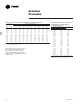
Performance Data Table PD-9 — Ratings of Security Wall Fin Copper/Aluminum Elements Without Enclosures Element Size Model 3 /4” 3CA4340 (19) Fin Size Fin Series Inches Per Foot (mm) Per Meter 4 1/4” x 3 5/8” 40 (108 x 92) (131 m) 3 /4” 3CA4350 (19) 4 1/4” x 3 5/8” (108 x 92) 50 (164 m) 1” 1CA4440 (25) 4 1/4” x 4 1/4” (108 x 108) 40 (131 m) 1” 1CA4450 (25) 4 1/4” x 4 1/4” (108 x 108) 50 (164 m) 1 1/4” 4CA4440 (32) 4 1/4” x 4 1/4” (108 x 108) 40 (131 m) 1 1/4” 4CA4450 (32) 4 1/4” x 4 1/4” (10
Performance Data Table PD-10 — Ratings of Security Wall Fin Steel Elements Without Enclosures Element Size Model 1 1/4” 4ST4440 (32) Fin Size Fin Series Inches Per Foot (mm) Per Meter 4 1/4” x 4 1/4” 32 (108 x 108) (105 m) 1 1/4” (32) 4ST4432 4 1/4” x 4 1/4” (108 x 108) 40 (131 m) 2” (51) 2ST4425 4 1/4” x 4 1/4” (108 x 108) 25 (82 m) 2” (51) 2ST4432 4 1/4” x 4 1/4” (108 x 108) 32 (105 m) Steam Capacity ]Hot Water Capacity Per Ft.
Dimensional Data Security Wall Fin Finned Tube Radiation Model S & F — Security Enclosures Partially Perforated Partially Perforated 5 5/16” (135 mm) 5 5/16” (135 mm) (51 mm) 2” PERFORATED AREA 3 /4” (19 mm) 2 1/32” (52 mm) 18” (457 mm) 12” (305 mm) 6” (152 mm) 2 TIER 18” (457 mm) ONLY 18” (457 mm) 12” (305 mm) 6” (152 mm) 2 TIER 18” (457 mm) ONLY /4” (19 mm) 1 3/8” (35 mm) FINISHED WALL (30 mm) 1 1/4” 1 3/8” (35 mm) FINISHED WALL PERFORATED AREA 3 6” (152 mm) 6” (152 mm) (52 mm) A A (52 m
Dimensional Data Fully Perforated Security Wall Fin Finned Tube Radiation Model S & F — Security Enclosures Fully Perforated 5 5/16” (135 mm) 5 5/16” (135 mm) (51 mm) 2” 1 3/8” (35 mm) FINISHED WALL FINISHED WALL 1 3/8” (35 mm) 18” (457 mm) 12” (305 mm) 18” (457 mm) 12” (305 mm) 6” (152 mm) 2 TIER 18” (457 mm) ONLY A 4” (MIN) (102 mm 6” (152 mm) 6” (152 mm) 2 TIER 18” (457 mm) ONLY 2 3/4” (70 mm) 3 /4” (16 mm) 21 2 /32” (67 mm) FINISHED FLOOR 6” (152 mm) 2 3/4” (70 mm) 4” (MIN) (102
Dimensional Data Slope Top — 12” (305) and 18” (457) 3” (76) End Cap 4” (102), 6” (152), 8 3/8” (213) End Trim 90º Inside Corner 2” Joiner Piece Dimensions shown in ( ) are in millimeters.
Dimensional Data Flat Top — 12” (305) and 18” (457) 3” (76) End Cap 4” (102), 6” (152), 8 3/8” (213) End Trim 90º Outside Corner 90º Inside Corner Dimensions shown in ( ) are in millimeters.
Dimensional Data 3 /4” CA (19) Copper- Aluminum — 40 Fins/Foot (131 Fins/Meter) /4” CA (19) Copper- Aluminum — 50 Fins/Foot (164 Fins/Meter) 3 NOTES: 1. Fins mechanically bonded to tube 2. Fin thickness is .020” (0.51) 3. Element lengths from 1’0” (0.30 m) through 8’0” (2.
Dimensional Data L 2 1/2" (64) 2-PLCS. Fins Per Ft. (m) F 15/16" (24) Threaded Ends NPT 4 1/4" (108) 1 1/4" (32) Nom. 1 1/4” ST (32) Steel Tube — Steel Fin — 40 Fins/Foot (131 Fins/Meter) 1 1/4” ST (32) Steel Tube — Steel Fin — 32 Fins/Foot (105 Fins/Meter) 4 1/4" (108) NOTES: 1. Fins mechanically bonded to tube 2. Fin thickness is .032” (0.81) 3. Element lengths from 1’0” (0.30 m) through 12’ (3.66 m) L 2 1/2" (64) 2-PLCS. F Fins Per Ft.
Models S and F Specifications Natural convection security wall fin shall be furnished to meet the specified capacity. Enclosure, heating elements and accessories shall be installed in accordance with the manufacturer’s recommendations. All enclosures shall be tamper-resistant. Mounting Hydronic security slope top and flat top wall fin enclosures shall be wallmounted 3 1/2” (89 mm) to 4” (102 mm) above the floor level to obtain catalog capacities.
Mechanical Specifications Security Enclosures • 1” CA (25 mm) •1 •1 Element Lengths 3 /4” CA (19 mm) elements shall be provided in 1’ (.3048 m) thru 8’ (2.44 m) lengths in 6” (.1542 m) increments. (Copper Tube-Aluminum Fin) The heating elements shall be constructed of seamless copper tubing mechanically expanded into aluminum fins. One tube end swaged for end-to- end joining. 4 1/4” x 4 1/4” (108 mm x 108 mm) size fins x .020” (.51 mm) fin thickness for maximum heat transfer.
Features and Benefits Model 11S Light Commercial Slope Top Wall Fin Enclosure The Trane hydronic light commercial slope top 11S wall fin line has been designed for natural convection to fill a void between less costly residential and commercial baseboard and the bigger and more expensive commercial wall fin enclosures and elements. 11S is a clean, reliable hydronic heat perimeter heating system that can be used as an economical primary or secondary heat source.
Features and Benefits Model 11S Inside Corner 6” (152 mm) End Cap With Access Door 6” (152 mm) Wall Trim 94 6” (152 mm) End Cap 8” (203 mm) Valve Compartment FIN-PRC004-EN
Features and Benefits Model 11S 14” (356 mm) Fill-In Section Outside Corner FIN-PRC004-EN 2” (51 mm) Splice Plate 95
Performance and General Data Model 11S English Units Table PD-1 — Copper/Aluminum Elements — Btu/Hour/Foot 11S Copper/Aluminum Elements Encl. Tube Fin Size Fins/ Fin Mtg.(2) Size Inches Foot Thickness Height (3) 3 /4” 2 1/4 x 2 1/2 50 0.011” 14 1/4” (3) 3 /4” 2 3/4 x 2 1/2 55 0.011” 14 1/4” *3/4” 2 3/4 x 3 3/4 50 0.011” 14 1/4” (3) 1” 2 3/4 x 2 1/2 55 0.011” 14 1/4” 1” 2 3/4 x 3 3/4 50 0.011” 14 1/4” 1” 2 3/4 x 5 40 0.020” 14 1/4” *1” 2 3/4 x 5 50 0.020” 14 1/4” 1 1/4” 2 3/4 x 3 3/4 50 0.
Performance and General Data Model 11S SI Units Table PD-4 — Copper/Aluminum Elements — Watts/Meter Copper/Aluminum Elements Tube Fin Size Fins/ Size Millimeters Meter (3) 19 mm 57 x 64 164 (3) 19 mm 70 x 64 180 *19 mm 70 x 95 164 (3) 25 mm 70 x 64 180 25 mm 70 x 95 164 25 mm 70 x 127 131 *25 mm 70 x 127 164 32 mm 70 x 95 164 *32 mm 70 x 127 131 32 mm 70 x 127 164 Fin Thickness 0.28 mm 0.28 mm 0.28 mm 0.28 mm 0.28 mm 0.51 mm 0.51 mm 0.51 mm 0.51 mm 0.51 mm Steam 11S Rating Encl. 102°C Mtg.
Dimensional Data One Tier (1) Notes: 1. Dimensions shown in [ ] are shown in millimeters. 2. Elements listed in Item 1 element descriptions are the only size elements that can be used in two-tier installations. Model 11S Two Tier (1,2) Item 1 2 3 4 5 6 7 8 Description Element — See Below Enclosure Bracket Mounting Channel Rod Hanger Rod Hanger Clip Fasteners By Others Slide Shoe Dwg. No. See Tab Box SRP-47072C SRP-47073C SRP-12930B 125BA Material As Specified 18 (1.2) Ga. CRS 14 (1,9) Ga. CRS 16 (1.
Dimensional Data Model 11S Accessories Valve Compartment Fill-In Section 90º Inside Corner 2” (51 mm) Splice Plate 90º Outside Corner 6” (152 mm) End Without Access Door Right Hand Shown — Left Hand Opposite FIN-PRC004-EN 3” (76 mm) End With Optional Piping Slot Right Hand Shown — Left Hand Opposite 6” (152 mm) End With Access Door Right Hand Shown — Left Hand Opposite 99
Cover and Accessory Layout Mou nting Chan nel Mounting Channel FIN-PRC004-EN Notes: 1. Enclosure sections available in following standard lengths: 2’ (.61 m) thru 8’ (2.4 m) in 1” (.3048 m) increments. 2. Dimensions shown in ( ) are in millimeters.
Mechanical Specifications General Natural convection light commercial slope top wall fin (Model 11S) shall be furnished to meet the specified capacity. Enclosure, heating elements, accessories, etc., shall be installed in accordance with the manufacturer’s recommendations. Mounting Hydronic light commercial slope top wall fin (Model 11S) shall be wall mounted 3 1/2” (89 mm) to 4” (102 mm) above the floor level to obtain catalog capacities. Enclosure Sloping top outlet.
Mechanical Specifications Heating Elements Copper Tube-Aluminum Fin (CA) CA heating elements are constructed of seamless copper tubing which has been mechanically expanded into aluminum fins. One tube is swaged for end-to-end joining. Fins are heat- reflecting and interlocked for maximum performance and optimum thermal contact. Six different combinations are available: 3 /4” (19 mm) CA Fin Size: 2 1/4” x 2 1/2” (57 mm x 64 mm) x .011” (.
The Trane Company An American Standard Company www.trane.com For more information contact your local district office or e-mail us at comfort@trane.com Literature Order Number FIN-PRC004-EN File Number PL-RF-FIN-000-PRC004-1001 Supersedes FIN-DS-1 4/98 Stocking Location La Crosse Since The Trane Company has a policy of continuous product and product data improvement, it reserves the right to change design and specifications without notice.