FURN-PRC001-EN Upflow/Horizontal Right or Upflow/Horizontal Left Induced Draft Gas Furnace XR 80 TUD040,060,080,100,120,140C Single-Stage Fan Assisted Combustion System PUB. NO.
General Features Natural Gas Models Central Heating furnace designs are certified by the American and Canadian Gas Associations for both natural and L.P. gas. Limit setting and rating data were established and approved under standard rating conditions using American National Standards Institute standards. Safe Operation The Integrated System Control has solid state devices, which continuously monitor for presence of flame, when the system is in the heating mode of operation.
Contents General Features 2 Features and Benefits 4 Standard Equipment Optional Equipment General Data TUD040C924K TUD040C930K TUD060C924K TUD060C936K TUD080C924K TUD080C936K TUD080C948K TUD080C960K TUD100C936K TUD100C945K TUD100C948K TUD100C960K TUD100C972K TUD120C954K TUD120C960K TUD140C960K 22-1640-06-0702 (EN) 4 5 6 6 6 6 6 7 7 7 7 8 8 8 8 9 9 9 9 Performance Data 10 Field Wiring 12 Twinning Field Wiring 13 Dimensions 14 Electrical Data 15 3
Features and Benefits XR 80 Upflow/Horizontal Right Or Left Standard Equipment • Power supply 115/1/60 • Cleanable high velocity filters • Multi-port In-shot burners • Standard filter sizes • Integrated solid state control with self diagnostics • Single wire twinning • Silicon Nitride hot surface igniter with adaptive heat up • Left-right gas connection • Complete front service access • Heavy guage aluminized steel heat exchanger • Selectable cooling fan off delay • Optional L.P.
Features and Benefits Optional Equipment Thermostat .............................................................................................................................................................. BAYSTAT388 [ Thermostat, Heating/Cooling Single Stage (Mounts Horizontally) ................................................................................ AY28X092 [ Thermostat, Heating/Cooling Single Stage (Mounts Vertically) .......................................................................
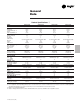
General Data Product Specifications 1 MODEL TYPE RATINGS 2 Input BTUH Capacity BTUH (ICS) 3 AFUE Temp. rise (Min.-Max.) °F. BLOWER DRIVE Diameter - Width (In.) No. Used Speeds (No.) CFM vs. in. w.g. Motor HP R.P.M. Volts / Ph / Hz COMBUSTION FAN - Type Drive - No. Speeds Motor HP - RPM Volts / Ph / Hz FLA FILTER — Furnished? Type Recommended Hi Vel. (No.-Size-Thk.) VENT — Size (in.) HEAT EXCHANGER Type -Fired -Unfired Gauge (Fired) ORIFICES — Main Nat. Gas. Qty. — Drill Size L.P. Gas Qty.
General Data Product Specifications 1 MODEL TYPE RATINGS 2 Input BTUH Capacity BTUH (ICS) 3 AFUE Temp. rise (Min.-Max.) °F. BLOWER DRIVE Diameter - Width (In.) No. Used Speeds (No.) CFM vs. in. w.g. Motor HP R.P.M. Volts / Ph / Hz COMBUSTION FAN - Type Drive - No. Speeds Motor HP - RPM Volts / Ph / Hz FLA FILTER — Furnished? Type Recommended Hi Vel. (No.-Size-Thk.) VENT — Size (in.) HEAT EXCHANGER Type -Fired -Unfired Gauge (Fired) ORIFICES — Main Nat. Gas. Qty. — Drill Size L.P. Gas Qty.
General Data Product Specifications 1 MODEL TYPE RATINGS 2 Input BTUH Capacity BTUH (ICS) 3 AFUE Temp. rise (Min.-Max.) °F. BLOWER DRIVE Diameter - Width (In.) No. Used Speeds (No.) CFM vs. in. w.g. Motor HP R.P.M. Volts / Ph / Hz COMBUSTION FAN - Type Drive - No. Speeds Motor HP - RPM Volts / Ph / Hz FLA FILTER — Furnished? Type Recommended Hi Vel. (No.-Size-Thk.) VENT — Size (in.) HEAT EXCHANGER Type -Fired -Unfired Gauge (Fired) ORIFICES — Main Nat. Gas. Qty. — Drill Size L.P. Gas Qty.
General Data Product Specifications 1 MODEL TYPE RATINGS 2 Input BTUH Capacity BTUH (ICS) 3 AFUE Temp. rise (Min.-Max.) °F. BLOWER DRIVE Diameter - Width (In.) No. Used Speeds (No.) CFM vs. in. w.g. Motor HP R.P.M. Volts / Ph / Hz COMBUSTION FAN - Type Drive - No. Speeds Motor HP - RPM Volts / Ph / Hz FLA FILTER — Furnished? Type Recommended Hi Vel. (No.-Size-Thk.) VENT — Size (in.) HEAT EXCHANGER Type -Fired -Unfired Gauge (Fired) ORIFICES — Main Nat. Gas. Qty. — Drill Size L.P. Gas Qty.
Performance Data FURNACE AIRFLOW (CFM) VS. STATIC PRESSURE (ins. w.g.) MODEL 0.10 0.20 0.30 0.40 0.50 0.60 0.70 0.80 0.90 TUD040C924K 4321- HIGH - Black MED.-HIGH - Blue MED.-LOW - Yellow LOW - Red 1018 847 716 617 1004 832 701 599 982 809 678 575 950 779 648 544 910 742 610 507 860 697 585 463 802 644 512 413 763 585 452 357 660 517 384 294 TUD040C930K 4321- HIGH - Black MED.-HIGH - Blue MED.
Performance Data FURNACE AIRFLOW (CFM) VS. STATIC PRESSURE (ins. w.g.) MODEL SPEED TAP 0.10 0.20 0.30 0.40 0.50 0.60 0.70 0.80 0.90 TUD100C972K BOTTOM AND LEFT SIDE RETURN 4321- HIGH - Black MED.-HIGH - Blue MED.-LOW - Yellow LOW - Red 2484 2458 2432 2387 2342 SEE NOTE 1 2275 2208 2125 2041 TUD100C972K 4321- HIGH - Black MED.-HIGH - Blue MED.
Field Wiring Field Wiring Diagram For Heating Only From Dwg. 21B341437 Rev. 1 Field Wiring Diagram For Single Stage Heating/Cooling (Outdoor Section Without Transformer) From Dwg. 21B341436 Rev.
Twinning Field Wiring From Dwg. 21B341422 Rev. 1 From Dwg. 21B341423 Rev.
TUD-C Outline Drawing (All dimensions are in inches) 14 22-1640-06-0702 (EN) From Dwg. 21C341699 Rev.
Electrical Data Schematic Diagrams for Gas Furnaces From Dwg. 21D341704 Rev.
Trane A business of American Standard Companies www.trane.com Literature Order Number FURN-PRC001-EN File Number — Supersedes TUD-D-1 3/98 Stocking Location PI Louisville & Webb/Mason-Houston 7/02 Trane has a policy of continuous product and product data improvement and it reserves the right to change design and specifications without notice. P.I.