
Installation and Maintenance Manual

Troubleshooting
GUNE-SVX001A-EN 37
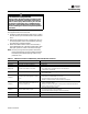
No cycling or appliance power or thermostat call for heat
since appliance failure has occurred:
1. Check the system thermostat to make sure it is calling
for heat. (Do not cycle the thermostat on and off at this
time.)
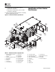
2. Remove the appliance burner compartment door. Do
not interrupt power to the control board by opening
any electrically interlocked panels.
3. Observe the LED indicator on the control board (a
green LED labeled “OK” indicates system faults); check
and repair system as noted in the chart to the right.
Note: Air flow proving switch and power venter hose
barbs must be free of any dust or debris at all times.
Periodically check these openings and/or if any
problems occur.
WARNING
Live Electrical Components!
Failure to follow all electrical safety precautions when
exposed to live electrical components could result in
death or serious injury. When necessary to work with
live electrical components, have a qualified licensed
electrician or other individual who has been properly
trained in handling live electrical components perform
these tasks.
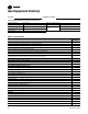
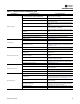
Table 15. Tubular duct furnace troubleshooting with LED indicator assistance
LED Status Indicates Check/Repair
Slow Flash Control OK, no call for heat. Not Applicable
Fast Flash Control OK, call for heat present. Not Applicable
Steady Off Internal control fault, or no power.
1. Line voltage on terminals 120 and C on transformer.
2. Low voltage (24 V) on terminals 24 and C on transformer.
3. 5 Amp fuse on circuit board.
Steady On Control internal failure or bad ground.
1. Common side of transformer grounded to chassis.
2. Loose spark ignitor.
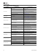
2 Flashes
In lockout from failed ignitions or flame
losses.
1. Gas supply off or gas supply pressure too low.
2. Flame sense rod contaminated or loose wire.
3. Gas valve switch is off or wires are not connected.
4. Broken or cracked porcelain on flame probe or spark ignitor.
3 Flashes
Pressure Switch open with inducer on or
closed with inducer off.
1. Obstructions or restrictions in appliance air intake or flue outlet are preventing
proper combustion airflow.
2. Moisture or debris in tubing that connects pressure switch and draft inducer.
3. Airflow switch jumpered or mis-wired.
4 Flashes Limit or rollout switch is open.
1. Open manual reset rollout switch.
2. Gas pressure too high, over fire condition.
3. Incorrect airflow due to blockage or motor not operating.
5 Flashes Flame sensed while gas valve is off. Flame probe mis-wired or shortened.
6 Flashes On-board microprocessors disagree. Thermostat is interfering with control board.