
Installation and Maintenance Manual

Installation: Mechanical
14 GHND-SVX01C-EN
Note: Refer to Figure 1, p. 7 through Figure 9, p. 14, and
dimensional data per Table 1, p. 10 for suspension
of units.
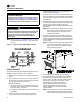
Nozzle Assembly
Use the following procedure for assembling the 30-, 60-, or
90-degree nozzle assembly to your unit heater.
1. Remove the louvers and the cone springs from the unit
heater.
2. Remove the four (4) screws from the upper section of
the front of the unit heater and use these same screws
to temporarily attach the top bracket
(P/N 252-07948-00X).
a. Using the holes in the top br
acket as a guide, pre-
drill a 1/8” (0.125”) hole at each location across the
front panel of the unit heater.
b. Using the enclosed screws, permanently attach the
top bracket.
3. Remove the upper two (2) s
crews from the lower
section on the front of the unit heater. Repeat the
procedure described in Step 2 using the bottom
bracket (P/N 252-07949-00X).
4. Using the sixteen (16) 5/16-1
2 x 1/2 screws, attach the
left and right side panel (P/N 251-07944 and 251-07946)
to the unit heater using the holes to which the louvers
were attached.
5. Using the enclosed #8-18 x 1/2
screws and with the top
panel oriented such that the side with the larger holes
is facing the unit heater, attach the top panel
(P/N 251-07942-00X) to the top brac
ket and the two (2)
side panels.
Note: Th
e top panel must be attached so that the side
with the larger holes is facing the unit heater;
this is a requirement for later steps in this
installation procedure.
6. Using the enclosed #8-18 x 1/2 screws and with the
bottom panel oriented such that the side with the larger
holes is facing the unit heater, attach the bottom panel
(P/N 251-07943-00X) to the bottom bracket and the two
(2) side panels.
Note: Th
e bottom panel must be attached so that the
side with the larger holes is facing the unit
heater; this is a requirement for later steps in
this installation procedure.
7. F
or 30-degree nozzle assemblies: Go to Step 10.
8. F
or 60- and 90-degree nozzle assemblies: Using the
enclosed #8-18 x 1/2 screws and with the top and
bottom panels oriented such that the sides with the
larger holes are facing the unit heater, create a
sub-assembly by attaching the top panel
(P/N 251-07942-00X) and the bottom panel
(P/N 251-07943-00X) to the left side panel
(P/N 251-07945) and to the right side pane
l
(P/N 251-07947).
Note: The top and bottom panels must be attached so
that the sides with the larger holes are facing
the unit heater; this makes the assembly easier.
NOTICE:
Equipment Damage!
Unit heaters must be hung level from side to side and
from front to back, see Figure 1, p. 7 and Figure 6, p. 11
through Figure 9, p. 14. Failure to do so could result in
poor performance and/or premature failure of the unit.
WARNING
Heavy Objects!
Ensure that all hardware used in the suspension of each
unit heater is capable of supporting the unit weight.
Failure to do so could result in unit falling off its
mounting location, which could result in death or
serious injury.
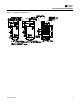
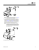
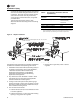
Figure 9. Heater mounting 100/400 MBtu unit sizes