
Installation and Maintenance Manual

Installation: Piping
18 GHND-SVX01C-EN
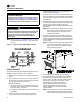
Pipe directly in to combination valve (see Figure 10,
p. 18).
5. A 1/8 in. N.P.T. plugged tapping, accessible for test
gauge connection, must be installed immediately
upstream of the gas supply connection to the
appliance.
6. Provide a drip leg in the gas piping near the gas unit
h
eater. A ground joint union and a manual gas shutoff
valve should be installed ahead of the unit heater
controls to permit servicing. The manual main shutoff
valve must be located external to the jacket (see
Figure 10, p. 18).
7. Make certain that all co
nnections have been
adequately doped and tightened.
Note: Use pipe joint sealant resistant to the action of
liquefied petroleum gases regardless of gas
conducted.
The appliance and its individual shutoff valve must be
disconnected from the gas supply piping system during
any pressure testing of that system at test pressures in
excess of 1/2 psig (3.5 kPa).
The appliance must be isolated from the gas supply piping
system by closing its individual manual shutoff valve
during any pressure testing of the gas supply piping
system at test pressures equal to or less than 1/2 psig
(3.5 kPa).
Installation: Venting
Venting for Power Vented (Category III)
Unit Heaters
All unit heaters must be vented!
All venting installations shall be in accordance with the
latest edition of Part 7, venting of Equipment of the
National Fuel Gas Code, ANSI Z223.1, or applicable
NOTICE:
Overtightening!
Do not overtighten the inlet gas piping into the valve.
This may cause stresses that could crack the valve!
WARNING
Hazard of Explosion!
Never use an open flame to detect gas leaks. Explosive
conditions may occur. Use a leak test solution or other
approved methods for leak testing. Failure to follow
recommended safe leak test procedures could result in
death or serious injury or equipment or property-only-
damage.
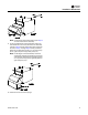
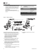
Figure 10. Pipe installation, standard controls
D 3 6 31 C
Table 4. Gas piping requirements
Gas Type Natural Gas Propane (LP) Gas
Single Stage Gas Piping Requirements
(a)
(a)For single stage applications only, at normal altitudes.
Manifold Pressure 3.5 in. wc 10.0 in. wc
(0.9 kPa) (2.5 kPa)
Supply Inlet Pressure 14.0 in. wc Max. 14.0 in. wc Max.
(3.5 kPa) (3.5 kPa)
5.0 in wc Min. 11.0 in wc Min.
(1.2 kPa) (2.7 kPa)
Two Stage Gas Piping Requirements
(b)
(b)For two stage applications only, at normal altitudes.
Supply Inlet Pressure 6.5 in. wc Min. 11.5 in. wc Min.
(1.6 kPa) (2.9 kPa)
WARNING
Carbon Monoxide!
Your venting system must not be blocked by any snow,
snow drifts, or any foreign matter. Inspect your venting
system to ensure adequate ventilation exists at all
times! A blocked venting system could result in carbon
monoxide poisoning. Symptoms of such condition
include grogginess, lethargy, inappropriate tiredness,
or flu-like symptoms. Failure to follow these
recommendations could result in death or serious
injury.
WARNING
Risk of Fire and Carbon Monoxide
Poisoning with Improper Piping!
Never use a pipe of a diameter other than that specified
in Table 1, p. 10! To prevent pipe from melting and
introducing exhaust fumes into the air supply, never
use PVC, ABS or any other non-metallic pipe for
venting! To prevent fan restriction, an elbow should
never be attached directly to the venter. Failure to
follow recommendations could result in death or
serious injury or equipment damage.