
Installation and Maintenance Manual

Installation: Piping
GHND-SVX01C-EN 19
provisions of local building codes for natural or power
vented units.
Power vented units are designed to be used with single
wall vent pipe utilizing horizontal or vertical venting
arrangements (see Figure 16, p. 23 through Figure 18).
These arrangements may terminate external to the
building using either a single wall or double wall vent. See
Figure 11, p. 20 through Figure 18, p. 23 for special
installation requirements regarding these venting
conditions.
If double wall venting (other than Type B; see preceding
warning) is used, components which are UL Listed and
approved for Category III positive pressure venting
systems MUST be used.
A Briedart Type L, Field Starkap or an equivalent vent cap
must be supplied by the customer for each power vented
unit. The vent pipe diameter MUST be as specified in
Tab l e 1 , p. 10 (“D” Dia. Flue Opening). A reducer must be
field installed for 100 through 175 MBh Unit Sizes. All 300
through 400 MBh Unit sizes are factory equipped with the
required flue increaser. Refer to Figure 11, p. 20 through
Figure 15, p. 22 for additional requirements.
The venting system for these appliances shall terminate at
least four feet (1.2 m) below, four feet (1.2 m) horizontal
from, or one foot (0.3 m) above any door, window, or
gravity air inlet into any building.
Through the wall vents for these appliances shall NOT
terminate over public walkways, or over an area where
condensate or vapor could create a nuisance or hazard or
could be detrimental to the operation of regulators, relief
valves, or other equipment.
The vent pipe equivalent length must be five feet (1.5 m)
minimum and must not exceed 50 feet (15.2 m).
Equivalent length is the total length of straight sections
PLUS 15 feet (4.6 m) for each 90 degree elbow, eight feet
(2.4 m) for each 45 degree elbow, and 10 feet (3.0 m) for
the vent cap.
Maintain six inches (152 mm) between vent pipe and
combustible materials. A minimum of 12 inches (305 mm)
of straight pipe is required from the venter outlet before
installing an elbow in the vent system. Never attach an
elbow directly to the venter (see preceding warning).
Use single wall pipe constructed of 26 gauge galvanized
steel or material of equivalent durability and corrosion
resistance for the vent system. For installation in Canada,
use pipe constructed from 0.025-inch thick aluminum or
0.018-inch thick stainless steel.
Any run of single wall vent pipe passing through an
unheated space must be insulated with an insulation
suitable to 550°F.
The vent terminal must be installed with a minimum
clearance of four feet (1.2 m) from electric meters, gas
meters, regulators and relief equipment.
Seal ALL vent pipe joints and seams to prevent leakage.
Use General Electric RTV-108 or Dow Corning
®
RTV-732
silicone sealant (or equivalent) or 3M #425 aluminum foil
tape or equivalent.
The vent system must be installed to prevent collection of
condensate. Vertical vent pipes should be equipped with
condensate drains. Pitch horizontal pipes downward 1/4
inch per foot (21 mm per m) toward outlet for condensate
drainage
Horizontal portions of the venting system shall be
supported at maximum intervals of four feet (1.2 m) to
prevent sagging (in Canada, support at three feet (1 m)
minimum intervals).
Insulate single wall vent pipe exposed to cold air or
running through unheated areas.
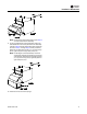
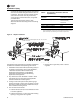
Units are shipped from the factory set up for vertical
venting. To convert the power venter for horizontal
venting, remove the shipping support bracket; refer to
Figure 11, p. 20, Figure 16, p. 23 through Figure 18, and
Figure 23, p. 35, and follow this procedure:
1. Hold power venter motor in position.
2. Remove the three Phillips-head screws from the motor
adaptor plate.
3. Remove the three screws
which connect the power
venter stack to the power venter housing.
4. Rotate the power venter h
ousing to the horizontal
position.
5. Replace screws accordingly.
Note: The motor, pressure switch, and junction box
bracket MUST remain located as shipped from the
factory for safe operation. Rotate only the blower
housing! If the power venter housing is to be
WARNING
Risk of Carbon Monoxide Poisoning with
Type B Vent!
Do not use a type B double wall vent internally within
the building on power vented units! Type B vent does
not seal well under positive pressure and could result in
exhaust fume leaks. Failure to follow these
recommendations could result in death or serious
injury.
WARNING
Carbon Monoxide!
Never operate unit heaters without combustion air and
flue gas piping in place. Each unit heater MUST have its
own combustion air system and MUST NOT be
connected to other vent systems or to a chimney. Your
venting system must not be blocked by any snow, snow
drifts, or any foreign matter. Inspect your venting
system to ensure adequate ventilation exists at all
times! Failure to follow these recommendations could
result in death or serious injury.