
Installation and Maintenance Manual

Start-Up
GHND-SVX01C-EN 29
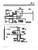
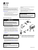
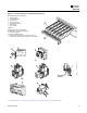
Figure 21. Burner components—intermittent pilot ignition
(a)
(a) Also refer to Figure 6, p. 11, Figure 10, p. 18, and Figure 3, p. 8 through Figure 5, p. 9 for component locations.
1
2
Burner Drawer Common Parts:
1. Main Burners
2. Burner Manifold
3. Air Shutters
4. Burner Springs
5. Main Burner Orifice
6. Transformer
7. Pilot Tubing
Controls:
8A.Main Gas Valve (Honeywell)
8B.Main Gas Valve (White-Rodgers)
9. Honeywell Ignitor
10. Honeywell Pilot Burner
13. High Limit (Safety device located on the rear
header plate of the heat exchanger, air inlet side.)
1
3
5
4
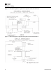
D4298A
8A
C
10
7
SPARK
1
M
V
2
MV/PV
3
4
GND
(BURNER
)
P
V
5
6
7
8
9
24V
(GND
)
24
V
TH-W
(OPT.
)
Honeywell
WARNING
S8600M
CONTINUOUS RE-TRY
100% SHUTOFF IP
90 SEC. TRIAL FOR IGNITION
9
8B
13
D3684A
6