Installation, Operation, and Maintenance Gas Unit Heater Separated Combustion Centrifugal Fan SAFETY WARNING Only qualified personnel should install and service the equipment. The installation, starting up, and servicing of heating, ventilating, and air-conditioning equipment can be hazardous and requires specific knowledge and training. Improperly installed, adjusted or altered equipment by an unqualified person could result in death or serious injury.
Warnings, Cautions and Notices Warnings, Cautions and Notices. Note that warnings, cautions and notices appear at appropriate intervals throughout this manual. Warnings are provide to alert installing contractors to potential hazards that could result in death or personal injury. Cautions are designed to alert personnel to hazardous situations that could result in personal injury, while notices indicate a situation that could result in equipment or property-damage-only accidents.
Warnings, Cautions and Notices WARNING Hazardous Service Procedures! The maintenance and troubleshooting procedures recommended in this manual could result in exposure to electrical, mechanical or other potential safety hazards. Always refer to the safety warnings provided throughout this manual concerning these procedures. When possible, disconnect all electrical power including remote disconnect and discharge all energy storing devices such as capacitors before servicing.
Introduction WARNING Safety Alert! You MUST follow all recommendations below. Failure to do so could result in death or serious injury. For Your Safety The use and storage of gasoline or other flammable vapors and liquids in open containers in the vicinity of this appliance is hazardous. If you smell gas: 1. Open windows. 2. Do not touch electrical switches. 3. Extinguish any open flame. 4. Immediately call your gas supplier from a neighbor’s phone. Follow the gas supplier’s instructions.
Table of Contents Warnings, Cautions and Notices . . . . . . . . . . 2 Model Number Descriptions . . . . . . . . . . . . . . 6 Indoor Gas Heating Units . . . . . . . . . . . . . . . 6 General Information . . . . . . . . . . . . . . . . . . . . . 7 Description . . . . . . . . . . . . . . . . . . . . . . . . . . . 7 General Safety Information . . . . . . . . . . . . . 7 Identification of Parts . . . . . . . . . . . . . . . . . . 8 Unit Dimensions and Weights . . . . . . . . . . .
Model Number Descriptions Indoor Gas Heating Units Digit 13 — Rooftop Heating Unit Motor Selection Note: All units are AGA approved. For CGA approved units, contact Air Handling Product Support.
General Information Description The Separated Combustion Gas Blower Unit Heater is a factory assembled, power vented, high static pressure type centrifugal blower unit designed for heavy duty applications, such as continuous operation, or where a single unit heater must do the entire heating job in a large area. Blower type unit heaters may be used with the standard adjustable louvers, or with short duct runs and discharge nozzles for spot heating.
General Information be inadvertently turned on. Failure to turn off gas or disconnect power before servicing could result in death or serious injury. • • When connecting to existing gas lines be sure to valve off the gas supply ahead of connection point. To avoid explosion or possible fire, always purge all residual gas from piping before cutting into existing line or removing threaded fittings. Failure to remove all gas vapors could result in death or serious injury or equipment or propertyonly-damage.
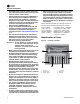
General Information Figure 3. Internal furnace assembly 1 2 3 1. Flue Collector 2. Heat Exchanger 3. Burner Drawer Figure 4. Separated Combustion Unit Heater 1 2 3 4 5 6 7 1. Pressure switch 5. Belt guard 2. Power vent assy. 6. Air inlet 3. Power vent motor 7. Gas supply inlet 4.
Unit Dimensions and Weights Table 1.
Unit Dimensions and Weights Figure 5.
Installation: Mechanical 4.9 m) in order to clear obstacles. When this is the case, it is advisable to use centrifugal blower unit heaters. NOTICE: Equipment Damage! Aircraft Hangers. Unit heaters must be installed in Do not install unit heaters in corrosive or flammable atmospheres! Premature failure of, or severe damage to the unit could result! Avoid locations where extreme drafts can affect burner operation.
Installation: Mechanical Figure 7. Heat throw distances Unit Heater Note: Unit heater sizing should be based on heat loss calculations where the unit heater output equals or exceeds heat loss. Heater output is approximately 80 percent of input Btu/hr rating. Clearances “H” Floor Line NOTICE: Maintain Minimum Thermostat Setting! Unit heaters should not be installed to maintain low temperatures and/or freeze protection of buildings. A minimum of 50°F (10°C) thermostat setting must be maintained.
Installation: Mechanical Note: Refer to Figure 1, p. 7 through Figure 9, p. 14, and dimensional data per Table 1, p. 10 for suspension of units. Figure 8. Heater mounting(a) 4. Using the sixteen (16) 5/16-12 x 1/2 screws, attach the left and right side panel (P/N 251-07944 and 251-07946) to the unit heater using the holes to which the louvers were attached. 5.
Installation: Mechanical Note: For 90-degree nozzle assemblies, repeat Step 8 to create a second sub-assembly. 9. For 60- and 90-degree nozzle assemblies: Using the enclosed #8-18 x 1/2 screws, attach the sub-assembly created in Step 8 to the 30-degree assembly installed to the unit (in Step 1 through Step 6 of this procedure). Attach the corresponding panels (i.e., top panel to top panel, right side panel to right side panel, etc).
Installation: Piping Gas Supply Piping WARNING Flammable Vapors! When connecting to existing gas lines be sure to valve off the gas supply ahead of connection point. To avoid explosion or possible fire, always purge all residual gas from piping before cutting into existing line or removing threaded fittings. Failure to remove all gas vapors could result in death or serious injury or equipment or property-only damage.
Installation: Piping Table 3. Gas pipe size(a) Nominal Internal 10 Iron Pipe Diameter, Size, in. in. (mm) (3.0) 1/2 Length of Pipe, ft (m) 20 (6.1) 30 40 50 60 70 80 90 100 125 150 175 200 (9.1) (12.2) (15.2) (18.3) (21.3) (24.4) (27.4) (30.5) (38.1) (45.7) (53.3) (61.0) 0.622 175 120 97 82 73 66 61 57 53 50 44 40 37 35 (16) (4.96) (3.40) (2.75) (2.32) (2.07) (1.87) (1.73) (1.61) (1.50) (1.42) (1.25) (1.13) (1.05) (0.99) 0.
Installation: Piping Pipe directly in to combination valve (see Figure 10, p. 18). 5. A 1/8 in. N.P.T. plugged tapping, accessible for test gauge connection, must be installed immediately upstream of the gas supply connection to the appliance. 6. Provide a drip leg in the gas piping near the gas unit heater. A ground joint union and a manual gas shutoff valve should be installed ahead of the unit heater controls to permit servicing.
Installation: Piping 1. The combustion air system installation must be in accordance with the latest edition of (N.F.P.A. 54) ANSI Z223.1 National Fuel Gas Code. In Canada, installation must be in accordance with CAN/CanGa-B149.1 “Installation Code for Natural Gas Burning Appliances and Equipment” and CAN/CanGa-B149.2 “Installation Code for Propane Burning Appliances and Equipment”. 2.
Installation: Piping 10. The top of a VERTICALLY VENTED exhaust system must extend at least three feet (1 m) above the roof surface that it passes through. The point of termination for a HORIZONTALLY VENTED exhaust system must be at least 12 inches (305 mm) from the exterior of the wall that it passes through.
Installation: Piping Figure 11. Vertical intake/vent installation Figure 14. Horizontal vent installation Installation: Concentric Vent Terminal WARNING Hazardous Service Procedures! Figure 12. Vertical vent installation The maintenance and troubleshooting procedures recommended in this manual could result in exposure to electrical, mechanical or other potential safety hazards. Always refer to the safety warnings provided throughout this manual concerning these procedures.
Installation: Piping Figure 15. Horizontal concentric venting Size pipes according to Table 1, p. 10. Insert the pipes through the wall and fasten the adapter box in place. Flash and/or caulk 8-inch pipe on outside wall (see Figure 16, p. 22, Step 3). Install the inlet air screen on the 8-inch pipe and fasten with sheet metal screws. Install the flue terminal on the 5-inch pipe and fasten in place (see Figure 16, p. 22, Step 4). Figure 16.
Installation: Piping Figure 17. Vertical concentric venting Figure 18. Vertical concentric venting—installation Size pipes according to Table 1, p. 10. Cut a hole through the roof for an 8-inch combustion air pipe. Fasten a length of 5-inch pipe to the exhaust connection of the concentric adapter with sheet metal screws. Use at least three screws per joint. Seal all joints with high temperature silicone sealant.
Installation: Electrical Electrical Connections WARNING Hazardous Service Procedures! The maintenance and troubleshooting procedures recommended in this section of the manual could result in exposure to electrical, mechanical or other potential safety hazards. Always refer to the safety warnings provided throughout this manual concerning these procedures. When possible, disconnect all electrical power including remote disconnect and discharge all energy storing devices such as capacitors before servicing.
Installation: Electrical Figure 19. C1267G, thermostat wiring diagram Thermostat Heat Anticipator Adjustments. The initial heat anticipator setpoint should equal the thermostat’s current amperage draw when the unit is firing. This setpoint should be measured for the best results. Use the recommended ranges as a guide. If further information is needed, consult your thermostat manufacturer’s instructions. Recommended Heat Anticipator Setting Ranges: 25 ft. (7.6 m) T’stat Wiring 0.85 to 0.90 A 50 ft. (15.
Start-Up Blower Set Up The drive ratio of the motor and blower sheaves has been preset at the factory for a temperature rise of 65°F at 0” wc with no external duct work on system. If the unit is to be operated under different air flow or pressure requirements, the drive ratio must be altered by means of the adjustable sheave on the blower motor (see Figure 20, p. 26). 1. Ensure that all packing material, support blocks, etc. have been removed from the unit. 2.
Start-Up Operation and ignition systems to control the temperature of the space being heated. Explanation of Controls (see Figure 20, p. 26) Note: The thermostat must be mounted on a vertical, vibration-free surface, free from air currents, and in accordance with the furnished instructions. WARNING Carbon Monoxide! Never operate unit heaters if the power venter is not operable. Your venting system must not be blocked by any snow, snow drifts, or any foreign matter.
Start-Up Figure 21. Burner components/unit controls (intermittent pilot ignition) Burner Drawer Common Parts: 1. 2. 3. 4. 5. 6. 7. Main Burners Burner Manifold Air Shutters Burner Springs Main Burner Orifice Transformer Pilot Tubing 1 Controls (refer to “Wiring Diagrams,” p. 41): 8A. Main Gas Valve (Honeywell) 8B. Main Gas Valve (White-Rodgers) 9. Honeywell Ignitor 10. Honeywell Pilot Burner 11. Honeywell Pilot Orifice 12. Honeywell Electrode/Sensor Lead 13.
Start-Up Checking Unit Heater Gas Input Rate Table 6. Type of Gas Natural NOTICE: Overfiring! Never overfire the unit heater, as this could cause unsatisfactory operation, or shorten the life of the heater. Gas appliances are rated based on sea level operation, with no adjustment required at elevations up to 2000 feet (610 m). At elevations above 2000 feet (610 m), input ratings should be reduced by 4 percent for each 1000 feet (305 m) above sea level. Check the input rate as follows: 1.
Start-Up Figure 22. Main burner flames NORMAL (HARD FLAME) YELLOW TIPPING (MARGINAL) LIFTING (TOO MUCH AIR) YELLOW FLAME (TOO LITTLE AIR) Pilot Adjustment 1. Remove the pilot adjustment cap. 2. Adjust the pilot screw to provide a properly sized flame. 3. A proper pilot flame is a soft steady flame that envelops 3/8- to 1/2-inch (9.5 to 12.7 mm) of the flame sensor. 4. Replace the pilot adjustment cap.
Start-Up Gas Equipment Start-Up Customer _____________________________________________ Job Name & Number _________________________ Pre-Inspection Information with Power and Gas Off Type of Equip: Indoor Unit Heater Serial Number: _________________________ Model Number: _____________________________ Name Plate Voltage: ____________________ Name Plate Amperage: ______________________ Type of Gas: Tank Capacity: Natural LP _______ lb Rating: _______ kg _______ Btu @ ____ °F ________ kW @ ____ °
Maintenance WARNING Hazardous Service Procedures! The maintenance and troubleshooting procedures recommended in this section of the manual could result in exposure to electrical, mechanical or other potential safety hazards. Always refer to the safety warnings provided throughout this manual concerning these procedures. When possible, disconnect all electrical power including remote disconnect and discharge all energy storing devices such as capacitors before servicing.
Maintenance 12. Check lubrication instructions on the motor. If oiling is required, add 3 to 4 drops of electric motor oil as follows: a. Light Duty—After 3 years or 25,000 hours of operation. b. Average Duty—Annually after 3 years or 8,000 hours of operation. c. Heavy Duty—Annually after 1 year or at least every 1,500 hours of operation. NOTICE: Equipment Damage! Never over oil the motor or premature failure could occur! 13.
Maintenance Figure 23. Power venter assembly Ref. No. Description Ref. No. Description 1 Blower Housing Assembly 15 Snap Bushing 2 Speed Nut 16 Relay (Motor) 3 Motor 17 Draftor Stack Assembly 4 Washer, Plain 18 Tubing (Aluminum) Formation 5 Plate Adapter 19 Male Connector 6 Blower Wheel (see Note 1) 20 Locknut 7 Mounting Bracket (Pressure Switch) 21 Hole Plug 8 Mounting Bracket (Junction Box) 22 Pressure Switch Cover 9 Screw, S.T.
Maintenance Installation Instructions for Field Replacement of Power Venter Motor WARNING Hazardous Voltage and Gas! Important: This replacement must be performed only by a qualified technician. Note: All hardware (screws, nuts, washers) that will be removed from the unit will be reused for this motor replacement. DO NOT LOSE ANY OF THESE PARTS. Turn off the gas supply and disconnect all electric power, including remote disconnects before servicing unit.
Maintenance • Remove the Blower Wheel (Item 9) from the motor shaft by removing the set screw (Item 14) using a 1/8-in. Allen Wrench. • Remove the three Motor Mounting Nuts (Item 5), Space Washers (Item 11), and Screws (Item 12). Do not lose these parts! Using caution—the motor will disengage from the Mounting Adapter Plate, along with the Relay Junction Box and Pressure Switch Mounting Brackets will also disengage. • Reverse order to install the new Power Venter Motor.
Diagnostics Troubleshooting WARNING Hazardous Service Procedures! The maintenance and troubleshooting procedures recommended in this section of the manual could result in exposure to electrical, mechanical or other potential safety hazards. Always refer to the safety warnings provided throughout this manual concerning these procedures. When possible, disconnect all electrical power including remote disconnect and discharge all energy storing devices such as capacitors before servicing.
Diagnostics Table 7. Troubleshooting guide (continued) Symptoms Possible Cause(s) Corrective Action F. 1. Shut off gas supply immediately! 1. Inspect all gas piping and repair. 2. Blocked heat exchanger/venting. 2. Clean heat exchanger/flue. 3. Drafts around heater. 3. Eliminate drafts. Refer to “Installation: Mechanical,” p. 12. 4. Negative pressure in building. 4. See “Installation: Piping,” p. 16. Clean flue collector. Gas Odor. G. Delayed ignition. H. Failure to ignite. 5.
Diagnostics Table 7. Troubleshooting guide (continued) Symptoms N. Fan will not run. O. Fan motor turns on and off while burner is operating. P. Fan motor will not stop. Q. Not enough heat. R. Too much heat. Possible Cause(s) Corrective Action 2. 2. Pilot adjustment screw turned too low on combination/automatic main gas valve. Refer to “Operation,” p. 27. 3. Air in gas line. 3. Purge air from gas supply. 4. Incorrect lighting procedure. 4.
Diagnostics Table 7. Troubleshooting guide (continued) Symptoms Possible Cause(s) U. No Spark. 1. Thermostat not calling for heat. 1. Close thermostat contacts. 2. No low voltage. 2. Check for 24V across 24V terminals of S8600. 3. Spark gap closed or too wide. 3. Set gap to 0.1. 4. Broken or cracked ceramic on spark electrode. 4. Replace pilot assembly. 1. Loose S8600 connections. 1. Check all connections, term. PV feeds 24V to pilot valve. 2. Improper gas pressure. 2.
Wiring Diagrams LADDER SEPARATED COMBUSTION UNIT PICTORIAL KEY CAUTION COLOR KEY Figure 25. Separated combustion unit, 100–400 blower, 100–250 prop.
Wiring Diagrams LADDER SEPARATED COMBUSTION UNIT PICTORIAL KEY CAUTION COLOR KEY Figure 26.
Trane optimizes the performance of homes and buildings around the world. A business of Ingersoll Rand, the leader in creating and sustaining safe, comfortable and energy efficient environments, Trane offers a broad portfolio of advanced controls and HVAC systems, comprehensive building services, and parts. For more information, visit www.Trane.com. Trane has a policy of continuous product and product data improvement and reserves the right to change design and specifications without notice.