
Catalogue

20 UH-PRC002-EN
General Data
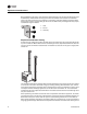
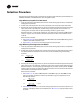
Service Clearances
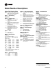
Heat Throw Data
Table 2. Minimum clearances
Duct Furnace Propeller & Centrifugal Fan U.H.
Sides 18” 18”
Top 6” 6”
Bottom 21”
(a)
21”
Flue 6” 6”
(a)21” clearance is required for bottom access to burners and pilot. If a side pull-out burner drawer is ordered (duct furnace only), bottom clearance can
be reduced to six inches. Side clearance, however, must be increased such that it is adequate for burner drawer removal. Reference Table 27, p. 53.
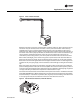
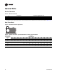
Figure 5. Standard unit heater applications
Table 3. Standard unit heater—approximate distance of throw at nominal airflow
Distance From
Floor to Bottom
of Unit “H”
ft (m)
Unit Size
Input MBh (kW)
30 45 60 75 100 125 150 175 200 225 250 300 350 400
(8.8) (13.2) (17.6) (22.0) (29.3) (36.6) (43.9) (51.2) (58.6) (65.9) (73.2) (87.8) (102.5) (117.1)
8 3333334060657075808590105110120
(2.4) (10.1) (10.1) (10.1) (12.2) (18.3) (19.8) (21.3) (22.9) (24.4) (25.9) (27.4) (32.0) (33.5) (36.6)
10 28 28 28 35 54 56 60 64 68 72 78 90 95 100
(3.0) (8.5) (8.5) (8.5) (10.7) (16.5) (17.1) (18.3) (19.5) (20.7) (21.9) (23.8) (27.4) (29.0) (30.5)
12 — — — — 44 46 49 57 61 65 68 80 84 90
(3.7) (13.4) (14.0) (14.9) (17.4) (18.6) (19.8) (20.7) (24.4) (25.6) (27.4)
15 ——————4549525660707480
(4.6) (13.7) (14.9) (15.8) (17.1) (18.3) (21.3) (22.6) (24.4)
20 ————————465054636670
(6.1) (14.0) (15.2) (16.5) (19.2) (20.1) (21.3)