
Catalogue


UH-PRC002-EN 39
Sequence of Operations
High-Efficiency Units
Note: On duct furnaces, the fan motor and associated controls shown in the wiring diagrams are
not integral to the unit. It is essential, however, that the air handling system be interlocked
with the duct furnace to prevent duct furnace operation without airflow.
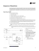
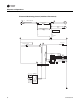
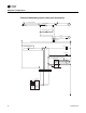
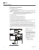
Single-Stage Control, Intermittent Pilot
With power applied to the unit:
1. The thermostat calls for heat.
2. The pressure switch measures the flow through the vent system and energizes the intermittent
pilot when the flow is correct.
Important: CAUTION: THE PRESSURE SWITCH MUST NOT BE BYPASSED. THE UNIT MUST
NOT BE FIRED UNLESS THE FLUE VENT FAN IS OPERATING. If this procedure is not
followed, there may be a gas buildup that could cause an explosion.
3. The pressure switch closes and activates the flue vent fan.
4. The pilot valve opens.
5. The ignitor sparks continuously to ignite the pilot.
6. The sensor proves pilot ignition and shuts off the ignitor.
7. With the pilot lit, the main gas valve opens.
8. Main burners are lit at 100 percent of the unit’s rated input.
9. The fan time delay relay allows the heater to come up to operating temperature. At this time,
the fan time delay relay closes and activates the fan motor.
1
10. The unit continues to fire until the thermostat is satisfied and no longer calls for heat.
11. The main and pilot valve close.
12. The fan time delay relay remains closed, keeping the fan operating to dissipate residual heat
from the heat exchanger. At this time, the fan time delay relay opens and deactivates the fan
motor.
1
See “Fan Control,” p. 30.
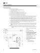
• Caution - Disconnect power before
servicing.
• Unit must be grounded.
• Use copper conductors only.
• If any of the original wire as supplied
with the appliance must be replaced,
it must be replaced with wiring
material having a temperature rating
of at least 125°C.
• High-limit wires minimum 200°C.
• Refer to installation instructions for
venting, gas piping and start-up
procedures.
• - - - Indicates Field Wiring.
• ___ Indicates Factory Wiring.
L2
L1
L1
L1
L1
8
LINE IN
115-240/1/60
TIME DELAY
SUMMER
WINTER
RELAY 1
L2
L2
BLOWER
MOTOR
T1
115-240/24V
50VA
DRAFTOR
MTR.
2
1
R
R
W
W
THERMOSTAT
HIGH LIMIT
1
3
2
DRAFTOR
PRESS. SW.
58600
IGNITOR
MV SOL.
MV
MV/PV
PV
GND
24V (HOT)
24V (GND)
SPARK
IGN
PV SOL.
RELAY 1
R
TIME DELAY
TD