Installation Operation & Maintenance Library Product Section Product Model WSHPC-IOM-2 72-9041-02 Service Literature Unitary Water Source Heat Pump GSSD Literature Type Sequence Date Installation, Operation and Maintenance 2 June 1999 File No. Supersedes SL-UN-WSHP-GSSD-IOM-2-6-99 WSHPC-IOM-2 / 72-9041-01 (Jan 98) Water Source Heat Pump Residential Split Configuration HVAC System ©An American Standard Company Since American Standard Inc.
Table of Contents Model Number Descriptions..................... 3 Installation (Water Loop).. 15 General Information...................... 4 Refrigeration Charge........ 16 Receiving and Handling.......................... 6 Refrigeration System....... 17 Installation Drawings......................... 7 Accessories................... 18 Installation (Water Connections).................... 10 Installation (Electrical)................. 11 Diagram....................
Model Number Description GS S D 036 1 0 C 0 0 1 2 0 T 10 5 DIGITS 1 & 2 - PRODUCT TYPE GS = Ground Source Heat Pump DIGIT 14 - FREEZE PROTECTION 1 = 35 Degree Freezestat DIGIT 3 - PRODUCT CONFIGURATION 2 = 20 Degree Freezestat S = Split System DIGIT 15 - OPEN 0 = Open DIGIT 4 - DEVELOPMENT SEQUENCE D DIGITS 5,6 & 7 - UNIT NOMINAL CAPACITY (MBH) DIGIT 16 - BRAND C = Command Aire T = Trane 024 = 24.1 030 = 29.6 036 = 36.4 042 = 41.1 048 = 48.7 060 = 59.2 072 = 65.
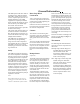
General Information The GSSD split unit has been ARI rated with the Trane TWE air handlers with ICM 2 variable speed motors to create a complete split system for residential applications. The GSSD equipment is completely assembled, piped, internally wired and test operated in the factory. The GSSD equipment is ETL and CSA listed. A prewired terminal strip is provided for field control wiring.
General Information Warranty The unit is warranted by the manufacturer against any defects in material and factory workmanship for one year after installation (labor and parts). The refrigerant circuit, including the compressor, expansion device, reversing valve (less solenoid coil), and all heat exchangers in contact with refrigerants are warranted for an additional four years (parts only). 5 Optional extended warranties are available through the local distributor.
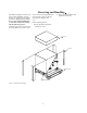
Receiving and Handling The GSSD is packaged in clear stretch wrap to allow immediate visual inspection. A careful inspection should be made for shipping damage. All orders are free on board (FOB) factory, therefore claims must be made with the delivering carrier. Carefully remove the stretch wrap and the top cardboard corner pieces. Also remove the (4) four shipping brackets from the lower corners of the unit along with the shipping skid.
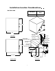
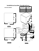
Installation-Location Considerations Unit Size 024 Unit Size Unit Weight (lbs.) 024 163 23-5/16” 23” 6-7/16” 5-1/2” LOW VOLTAGE 1-1/8” DIA. TOP VIEW 3-15/16” 1-7/16” PUMP CONTROL 1-1/8” DIA. WATER REG (SCHRADER PORT) HI VOLTAGE 1-1/8” DIA. SUCTION/DISCH 3/4” O.D. LIQUID LINE 1/2” O.D.
Installation-Location Considerations Unit Size 030-042 Unit Size Unit Weight (lbs.) 030 169 036 183 042 203 23-5/16” 23” 6-7/16” 5-1/2” LOW VOLTAGE 1-1/8” DIA. TOP VIEW 3-15/16” 1-7/16” PUMP CONTROL 1-1/8” DIA. WATER REG (SCHRADER PORT) HI VOLTAGE 1-1/8” DIA. SUCTION/DISCH 3/4” O.D. LIQUID LINE 1/2” O.D.
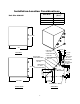
Installation-Location Considerations Unit Size 048-072 Unit Size Unit Weight (lbs.) 048 214 060 244 072 277 23-5/16” 6-7/16” 5-1/2” 23” LOW VOLTAGE 1-1/8” DIA. PUMP CONTROL 1-1/8” DIA. WATER REG (SCHRADER PORT) SUCTION/DISCH 3/4” O.D. DESUPER OUT 1/2” NPT DESUPER IN 1/2” NPT LO PSI SCHRADER 24-5/16” 10-7/16” 7-3/16” HI PSI SCHRADER 8-7/16” 11-1/2” 24-13/16” WATER IN-1” NPTI FRONT VIEW SIDE VIEW 9 13-15/16” 14-3/4” 19-1/16” 3-15/16” 1-7/16” HI VOLTAGE 1-1/8” DIA. LIQUID LINE 1/2” O.D.
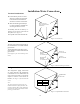
Installation-Water Connections Location Consideration ! Unit should be placed on a level surface in a indoor protected area. Units should not be installed or stored in an exterior environment. ! There should be approximately 2 to 3 feet of clearance available for accessing the unit for service. Remove these two screws for internal unit maintenance. Accessiblity into unit is made by removing (2) two screws at the base of the system. (See Figure 2). The top half of the cube then lifts off.
Installation- Electrical Field Wiring Connections Power wiring to the unit should be installed per local electric codes by a professional electrician. The wires can be run to the unit through the available knockouts and to the control box in the top half of the unit. Control wiring to the unit is 24 volt. The termination point identifications for the terminal strip is identified per Figure 5.
Installation- Electrical Electrical System 24VAC ENERGY LIMITING CLASS II 75VA BREAKER TYPE TRANSFORMER LOCKOUT RELAY; 24VAC The factory tested and installed control box contains all of the necessary devices to control unit operation in both the heating and cooling mode. A remote wall thermostat is necessary for the control of the unit operation. See General Information for thermostat information.
Installation- Electrical Pressure Switch der low charge or catastrophic loss of charge situations. A high pressure switch is provided to protect the compressor against excessive refrigeration pressure. The low pressure switch should be wired in accordance with the type of freezestat that is used. Trane factory supplies two low pressure switches in the refrigerant circuit.
Typical Wiring Diagram L2 L1 230V 6A MAX TO WATERSOURCE PUMP 5F3 5F2 6E 1K1 L3 5F1 2A 6F 6H A C 1C1 1K1 4S5 6G 4S6 DESUPERHEATER PUMP 7C 6A,C,D,E T3 L1 4 A,C S A T1 6B1 R 7A 2B1 5C C 5C G 1TB3-1 F,G 16 1TB3-5 A 1K3 C2 C1 18 1TB3-2 C 1K319A 4S3 20A 4S4 4S1 21A 5 A 23 1TB3-7 23 A 16 D,F 1K1 1K3-24 D 1TB3-8 1K1-12,14 1TB3-6 A 4S4 F 25 LEGEND DEVICE 1K1 1K3 DESCRIPTION NOTES: 1. COMPRESSOR CONTACTOR LOCKOUT RELAY 2.
Installation - Water Loop Loop Water Applications It should be noted that there is no mechanical difference between geothermal (closed loop) and ground water (open loop) GSSD units. Generally in a closed loop application, there is a percentage of antifreeze in the water. In these applications, the 20 degree F freezestat, along with the 7 psig safety pressure switch may be used. All other applications require the 35 degree F freezestat, along with the 35 psig safety pressure switch.
Refrigerant Charge GSSD Units Coupled with TWE Air Handlers 3. Table 5: R22 requirement per foot of line The GSSD IS coupled with the TWEE series. Table 4 may be used to determine the amount of charge necessary for the split unit system without any refrigerant line connecting the two. Table 5 can be used to determine the amount of refrigerant needed for lines. By adding the two weights together, the approximate total system charge can be obtained.
Refrigeration System ! Compressor: The unit includes a high efficiency scroll compressor with and internal vibration isolator that absorbs starting and stopping energy. It also contains an internal overload protection. External vibration isolation is provided by rubber mounting devices located underneath the mounting base of the compressor. ! Water-to-Refrigerant Heat Exchanger: The water-torefrigerant heat exchanger is a high quality stainless steel braze plate heat exchanger.
Miscellaneous Equipment Accessory Items Note: The following equipment may be purchased through the nearest Trane distributor. ! Water Regulating Valve Assembly: The water regulating valve assembly consists of a direct acting valve and a reverse acting valve. The direct acting valve opens in response to an increase in discharge pressure during the cooling cycle. The reverse acting valve opens in response to a decrease in suction pressure during the heating cycle.