Installation, Operation, and Maintenance Water Source Heat Pump Axiom™ Horizontal/Vertical GEHE/GEVE, EXHF/EXVF ½ to 25Tons, 50/60 Hz Model Numbers GEHE 006-060 - 50/60 Hz GEHE 072-120 - 50/60 Hz EXHF 006-070 - 60 Hz GEVE 006-060 - 50/60 Hz GEVE 072-300 - 50/60 Hz EXVF 006-070 - 60 Hz SAFETY WARNING Only qualified personnel should install and service the equipment.
Introduction Read this manual thoroughly before operating or servicing this unit. Warnings, Cautions, and Notices Safety advisories appear throughout this manual as required.Your personal safety and the proper operation of this machine depend upon the strict observance of these precautions. The three types of advisories are defined as follows: Indicates a potentially hazardous situation which, if not avoided, could result in death or serious injury.
Introduction Copyright This document and the information in it are the property of Trane, and may not be used or reproduced in whole or in part without written permission.Trane reserves the right to revise this publication at any time, and to make changes to its content without obligation to notify any person of such revision or change. Trademarks All trademarks referenced in this document are the trademarks of their respective owners.
Table of Contents Introduction . . . . . . . . . . . . . . . . . . . . . . . . . . . . . 2 Warnings, Cautions, and Notices . . . . . . . . 2 Supply/Return Pipe Connections . . . . . . .60 Important Environmental Concerns . . . . . 2 Cleaning and Flushing the Water Loop . .61 Important Responsible Refrigerant Practices 2 Field Installed Power Wiring . . . . . . . . . . .61 Types of Hose Connections . . . . . . . . . . . .60 Main Unit Power Wiring . . . . . . . . . . . . . .61 Copyright . . . . . . .
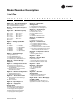
Model Number Description ½ to 5 Ton G E H E 0 0 6 1 1 * 0 1 B 0 B R D 0 1 0 0 0 0 1 0 0 1 2 3 4 5 6 7 8 9 10 11 12 13 14 15 16 17 18 19 20 21 22 23 24 25 26-36 Digits 1-3 — Unit Configuration GEH = Standard Efficiency Horizontal GEV = Standard Efficiency Vertical Digit 16 — Return-Air Arrangement Digit 4 — Development Sequence L = Left Return-Air Arrangement R = Right Return-Air Arrangement E = R-410A Digit 17 — Control Types Digits 5-7 — Nominal Cap
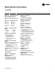
Model Number Description 6 to 25 Ton G E H E 0 7 2 1 1 * 0 A 0 0 A B D 0 0 0 0 0 0 1 0 1 2 3 4 5 6 7 8 9 10 11 12 13 14 15 16 17 18 19 20 21 22 23 24 25-36 Digits 1-3 - Unit Configuration Digit 13 - Freeze Protection GEH = High Efficiency Horizontal GEV = High Efficiency Vertical A = 20°F Freezestat B = 35°F Freezestat Digit 4 - Development Sequence Digit 14 - Open Digit = 0 E = R-410A Digits 5-7 - Nominal Capacity Digit 15 - Supply-Air Arrangement
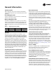
Model Number Description ½ to 6 Ton E X H F 0 0 6 1 1 * 0 3 B 0 B R D 0 1 0 0 0 0 1 0 0 1 2 3 4 5 6 7 8 9 10 11 12 13 14 15 16 17 18 19 20 21 22 23 24 25 26-36 Digits 1-3 — Unit Configuration EXH = High Efficiency Horizontal EXV = High Efficiency Vertical Digit 16 — Return-Air Arrangement Digit 4 — Development Sequence L = Left Return-Air Arrangement R = Right Return-Air Arrangement F Digit 17 — Control Types Digits 5-7 — Nominal Capacity 006 - 1/2 t
Overview of Manual Note: One copy of this document ships with each unit and is customer property. It must be retained by the unit’s maintenance personnel. This booklet describes proper installation, operation, and maintenance procedures for HVAC systems. By carefully reviewing the information within this manual and following the instructions, the risk of improper operation and/or component damage will be minimized.
General Information Unit Description Basic 24V Controls Before shipment, each unit is leak tested, dehydrated, charged with refrigerant and run tested for proper control operation. Safety devices for equipment containing the basic 24V control option include a low-pressure switch to prevent compressor operation during low temperature or low suction activity.The switch is set to activate at refrigerant pressure of 40 psig to fit most applications.
General Information Waterside Economizer (Option) Hot Gas Reheat (option) Instructions for mechanical connection of the waterside economizer to the water-source heat pump may be found in the dimensional section of this manual. With the reheat option, the return-air from the space is conditioned by the air-to-refrigerant coil, then reheated by the reheat coil to control not only the space temperature, but to also reduce the relative humidity of the space.
General Information Table 3. Refrigerant charge Model (60 Hz) Heat Pump (oz)/(Kg) Heat Pump w/HGR (oz)/(Kg) Circuit 1 Circuit 2 Circuit 1 GEHE006 25.3 / .717 ----- 26.8 / .760 Circuit 2 ----- GEHE009 26.0 / .737 ----- 27.5 / .780 ----- GEHE012 28.5 / .808 ----- 30.5 / .865 ----- GEHE015 29.0 / .822 ----- 30.5 / .865 ----- GEHE018 36.5 / 1.035 ----- 39.5 / 1.120 ----- GEHE024 39.0 / 1.106 ----- 42.0 / 1.191 ----- GEHE030 44.0 / 1.247 ----- 46.5 / 1.
General Information Table 3. Refrigerant charge (continued) Model (60 Hz) 12 Heat Pump (oz)/(Kg) Heat Pump w/HGR (oz)/(Kg) EXHF060 114.0 / 3.232 ----- 118.5 / 3.359 ----- EXHF070 122.0 / 3.459 ----- 127.0 / 3.600 ----- EXVF006 25.7 / 0.729 ----- 27.2 / 0.771 ----- EXVF009 26.5 / 0.751 ----- 28.0 / 0.794 ----- EXVF012 29.5 / 0.836 ----- 31.5 / 0.893 ----- EXVF015 30.0 / 0.850 ----- 32.0 / 0.907 ----- EXVF018 45.0 / 1.276 ----- 48.0 / 1.361 ----- EXVF024 52.0 / 1.
Pre-Installation Jobsite Storage WARNING Fiberglass Wool! Product contains fiberglass wool. Disturbing the insulation in this product during installation, maintenance or repair will expose you to airborne particles of glass wool fibers and ceramic fibers known to the state of California to cause cancer through inhalation. Glass wool fibers may also cause respiratory, skin or eye irritation. Unit Inspection Checklist • Unpack all components of the kit. • Check carefully for any shipping damage.
Unit Dimensions and Weights GEH and EXH Clearance Dimensions Access to the unit for service purposes should be provided at installation. All ½-5 tons and EXH070 configurations (see Figure 1, p. 14) require an 18 in. (457 mm) surround clearance from other mechanical and electrical equipment (where shown) to enable panel removal from the unit for service/maintenance ability. NEC requires 36 in. clearance on the control panel side of the unit.
Unit Dimensions and Weights GEV ½ to 5 tons and EXV ½ to 6 tons clearance dimensions Access to the unit for service purposes should be provided at installation. A 24 in. surround clearance (see Figure 3, p. 15) from other mechanical and electrical equipment (where shown) is recommended for all configurations. This will enable panel removal from the unit for service/ maintenance. Some local codes require a greater service clearance than listed below. Check all code requirements prior to unit installations.
Unit Dimensions and Weights Figure 6. Left return/left supply (GEH/EXH) P B TOP R S N A FXG OPENING H Q PANEL HI VOLT L (W.O.) WCI mounting location LO VOLT 1/2" (13) 3/4" (19) NPTI J H BACK LEFT SIDE D M (W.I.) 1" (25.4) K DRAIN 7" (178) ACCESS FRONT 1 3/8" (35) C REFRIG AND CONTROL ACCESS 6 3/4" (171) 1" (25.4) BLOWER E 14" (356") RIGHT SIDE Table 4.
Unit Dimensions and Weights Figure 7. Left return/back supply (GEH/EXH) P B TOP S R A 1"(25.4) C BLOWER H REFRIG AND CONTROL ACCESS ACCESS Q PANEL L (W.O.) HI VOLT WCI mounting location LO VOLT BACK LEFT SIDE D 1/2" (13) M (W.I.) 1" (25.4) J K H DRAIN 3/4" (19) NPTI 7" (178) OPENING FRONT E 1 3/8" (35) N 6 3/4" (171) FXG 14" (356) RIGHT SIDE Table 5.
Unit Dimensions and Weights Figure 8. Left return/right supply (GEH/EXH) P B TOP S R N A BLOWER ACCESS PANEL REFRIG AND CONTROL ACCESS Q L (W.O.) HI VOLT 7" (178) 1" (25.4) D 6 3/4" (171) E WCI mounting location 1" (25.4) BACK 1/2" (13) DRAIN 3/4" (19) NPTI LEFT SIDE FXG OPENING C 1 3/8" (35) M (W.I.) LO VOLT FRONT H 14" RIGHT SIDE K H Table 6.
Unit Dimensions and Weights Figure 9. Right return/left supply (GEH/EXH) S R P B TOP N A 1" (25.4) BLOWER ACCESS PANEL D FXG OPENING H REFRIG AND CONTROL ACCESS 6 3/4" (171) E Q HI VOLT WCI mounting location LEFT SIDE C L (W.O.) FRONT M (W.I.) 7" (178) DRAIN 3/4" (19) NPTI 1/2" (13) J BACK 1"(25.4) K LO VOLT H 14" (356) 1 3/8"(35) RIGHT SIDE Table 7.
Unit Dimensions and Weights Figure 10. Right return/back supply (GEH/EXH) S R P B TOP N A FXG OPENING 1" (25.4) C E D BLOWER ACCESS PANEL HI VOLT REFRIG AND CONTROL ACCESS 14" (356) Q WCI mounting location L (W.O.) J DRAIN 3/4" (19) NPTI BACK LEFT SIDE FRONT M (W.I.) 1" (25.4) 6 3/4" (171) 1/2" (13) LO VOLT H K 1 3/8" (35) RIGHT SIDE 7" (178) H Table 8.
Unit Dimensions and Weights Figure 11. Right return/right supply (GEH/EXH) S R P B TOP N A BLOWER ACCESS PANEL D 6 3/4" (171) 1" (25.4) E C REFRIG AND CONTROL ACCESS Q HI VOLT WCI mounting location LO VOLT FRONT L (W.O.) M (W.I.) 1/2" (13) DRAIN 3/4" (19) NPTI FXG OPENING 1" (25.4) LEFT SIDE BACK H Table 9.
Unit Dimensions and Weights Figure 12. Left return/top supply: GEVE—“A” and later design sequence; EXV—“A” and later design sequence D L F K D E M J TOP BLOWER ACCESS H B COMP/CONTROL ACCESS W.O. WCI mounting location DRAIN HI VOLT 8 3/4" (222) 12" 9 1/2" (305) (241) G 3 5/8" (92) LO VOLT 3 5/8" (92) LEFT SIDE W.I. A C FRONT RIGHT SIDE Table 10. Left return/top supply: GEVE—“A” and later design sequence; EXV—“A” and later design sequence W.I. W.O.
Unit Dimensions and Weights Figure 13. Left return/back supply: GEVE—“A” and later design sequence; EXV—“A” and later design sequence D E M j TOP F BLOWER ACCESS D H B COMP/CONTROL ACCESS WCI mounting location W.O. DRAIN HI VOLT 8 3/4" (222) 12" (305) LO VOLT 3 5/8" (92) 9 1/2" (241) G 3 5/8" (92) W.I. A LEFT SIDE C FRONT RIGHT SIDE Table 11.
Unit Dimensions and Weights Figure 14. Right return/top supply: GEVE—“A” and later design sequence; EXV—”A” and later design sequence) F D L K D E J M TOP BLOWER ACCESS H B COMP/CONTROL ACCESS W.O. WCI mounting location DRAIN HI VOLT LO VOLT 3 5/8" (92) 8 3/4" (222) W.I. C 3 5/8" (92) 12" 9 1/2" (305) (241) G A FRONT LEFT SIDE RIGHT SIDE Table 12. Right return/top supply: GEVE—“A” and later design sequence; EXV—“A” and later design sequence W.I. W.O.
Unit Dimensions and Weights Figure 15. Right return/back supply: GEVE—“A” and later design sequence; EXV—“A” and later design sequence F D L K D E J M TOP BLOWER ACCESS H B COMP/CONTROL ACCESS W.O. WCI mounting location DRAIN HI VOLT LO VOLT 3 5/8" (92) 8 3/4" (222) W.I. C 3 5/8" (92) 12" 9 1/2" (305) (241) G A FRONT LEFT SIDE RIGHT SIDE Table 13.
Unit Dimensions and Weights Figure 16. GEH 6-10 tons (072-120) 60 Hz; GEH 6-7½ tons (072-090) 50 Hz—right return/left supply 20" (508) SERVICE CLEARANCE 36" (914) SERVICE CLEARANCE 4 5/8" (117) 79" (2007) 74 1/2" (1892) 1 3/4" (44) 36" (914) 2 1/8" (54) 23 7/8" (606) BLOWER ACCESS PANEL 40 5/8" (1032) 7 5/8" (194) TOP VIEW 18 3/8" (467) 81" (2057) 85" (2159) 1 1/4" (32) 5/8" (16) W.O. "D" NPTI 1" (25.4) 24 VOLT 1 1/8" (28.6) DIA.
Unit Dimensions and Weights Figure 17. GEH 6–10 tons (072–120) 60 Hz; GEH 6–7½ tons (072–090) 50 Hz—right return/back supply 36" (914) SERVICE CLEARANCE 74 1/2" (1892) 1 3/4" (44) 36" (914) 18 3/8" (467) 81" (2057) 85" (2159) 6 1/8" (156) 2 1/8" (54) 23 7/8" (606) 4 5/8" (117) 79" (2007) BLOWER ACCESS PANEL 40 5/8" (1032) 20" (508) SERVICE CLEARANCE TOP VIEW 4 7/8" (124) 1 1/4" (32) 5/8" (16) W.O. "D" NPTI 24 VOLT 1 1/8" (28.6) DIA.
Unit Dimensions and Weights Figure 18. GEH 6-10 tons (072-120) 60 Hz; GEH 6-7½ tons (072-090) 50 Hz - left return/right supply 36" (914) SERVICE CLEARANCE 79" (2007) 4 5/8" (117) 40 5/8" (1032) 20" (508) SERVICE CLEARANCE 74 1/2" (1892) 1 3/4" (44) 36" (914) 24 3/4" (629) 1 1/4" (32) 7 5/8" (194) TOP VIEW BLOWER ACCESS PANEL 18 3/8" (467) 81" (2057) 85" (2159) 23 1/4" (591) 16 1/2" (419) A 1" (25.4) 5/8" (16) 24 VOLT 1 1/8" (28.6) DIA. 1 1/4" (32) W.O.
Unit Dimensions and Weights Figure 19. GEH 6-10 tons (072-120) 60 Hz; GEH 6-7½ tons (072-090) 50 Hz—left return/back supply 36" (914) SERVICE CLEARANCE 1 3/4" (44) 36" (914) 18 3/8" (467) 81" (2057) 85" (2159) 20" (508) SERVICE CLEARANCE 6 1/8" (156) 40 5/8" (1032) 74 1/2" (1892) 24 3/4" (629) 1 1/4" (32) 4 5/8" (117) 79" (2007) TOP VIEW BLOWER ACCESS PANEL 23 1/4" (591) 16 1/2" (419) A 5/8" (16) 24 VOLT 1 1/8" (28.6) DIA. 1 1/4" (32) W.O.
Unit Dimensions and Weights Figure 20. GEH 12½-15 tons (150-180) 60 Hz; GEH 10-12½ tons (120-150) 50 Hz—right return/left supply 20" (508) SERVICE CLEARANCE 36" (914) SERVICE CLEARANCE 4 5/8" (117) 79" (2007) 74 1/2" (1892) 1 3/4" (44) 36" (914) 2 1/8" (54) 23 7/8" (606) BLOWER ACCESS PANEL 40 5/8" (1032) 7 5/8" (194) TOP VIEW 18 3/8" (467) 81" (2057) 85" (2159) 24 VOLT 1 1/8" (28.6) DIA. A 1 1/2" (38) ) 4 7/8" (124) 1 1/4" (32) 5/8" (16) W.O. "D" NPTI 1" (25.
Unit Dimensions and Weights Figure 21. GEH 12½-15 tons (150-180) 60 Hz; GEH 10-12½ tons (120-150) 50 Hz—right return/back supply 36" (914) SERVICE CLEARANCE 74 1/2" (1892) 2" (41) 46 5/8" 42" (1184) (1067) 21 3/8" (543) 87" (2210) 91" (2311) 7 1/8" (181) 2 1/4" (57) 29 3/4" (756) 4 5/8" (117) 85" (2159) 20" (508) SERVICE CLEARANCE TOP VIEW W.O. 1 1/2" (38) NPTI 24 VOLT 1 1/8" (28.6) DIA.
Unit Dimensions and Weights Figure 22. GEH 12½-15 tons (150-180) 60 Hz; GEH 10-12½ tons (120-150) 50 Hz—left return/right supply 36" (914) SERVICE CLEARANCE 85" (2159) 4 5/8" (117) 74 1/2" (1892) 2" (51) 42" (1067) 29 3/4" (756) 7 1/8" (181) TOP VIEW 2 1/4" (57) 46 5/8" (1184) 20" (508) SERVICE CLEARANCE BLOWER ACCESS PANEL 21 3/8" (543) 87" (2210) 1" (25.4) 4 7/8" (124) 16 3/4" (425) WCI mounting location 23 3/4" (603) 24 7/8" (632) HIGH VOLTAGE 7/8" (22.2) DIA.
Unit Dimensions and Weights Figure 23. GEH 12½-15 tons (150-180) 60 Hz; GEH 10-12½ tons (120-150) 50 Hz—left return/back supply 36" (914) SERVICE CLEARANCE 2" (51) 42" (1067) 21 3/8" (543) 87" (2210) 91" (2311) 20" (508) SERVICE CLEARANCE 29 3/4" (756) 7 1/8" (181) 46 5/8" (1184) 74 1/2" (1892) 2 1/4" (57) 4 5/8" (117) 85" (2159) TOP VIEW BLOWER ACCESS PANEL 4 7/8" (124) 16 3/4" (425) WCI mounting location 23 3/4" (603) 24 7/8" (632) HIGH VOLTAGE 7/8" (22.2) DIA. LEFT SIDE W.I.
Unit Dimensions and Weights Figure 24. GEV 6-10 tons (072-120) 60 Hz; 6 and 7½ tons (072 and 090) 50 Hz—front return/back supply(a) 15 3/4 (400) ACCESS PANEL FOR SHEAVES AND BELTS SUPPLY OPENING 1" (25.4) DUCT FLANGE 13 18" (333) 36" (914) SERVICE CLEARANCE 39 5/8" (1006) 42" (1067) 20" (508) SERVICE CLEARANCE 4 7/8" (124) 31 3/8" 36 1/4" (797) (921) 1 (25.4) 13 1/2" (343) 38 7/8" (987) 62 5/8" (1591) W.O. "C" NPTI 24 VOLT 1 1/8" (28.
Unit Dimensions and Weights Figure 25. GEV 6–10 tons (072–120) 60 Hz; 6 and 7½ ton (072 and 090) 50 Hz—front return/top supply(a) ACCESS PANEL FOR SHEAVES AND BELTS 1 1/8" (29) 15 5/8 (397) 13 1/4" (337) 13 3/8" (343) 36" (914) SERVICE CLEARANCE 39 5/8" (1006) 42" (1067) 1" (25.4) 20" (508) SERVICE CLEARANCE 4 7/8" (124) 31 3/8" 36 1/4" (797) (921) 63" (1600) 38 7/8" (987) W.O. "C" NPTI 24 VOLT 1 1/8" (28.6) HIGH VOLTAGE 7/8" (22.2) DIA.
Unit Dimensions and Weights 4 7/8" (124) Figure 26. GEV 6–10 tons (072-120) 60 Hz; 6 and 7½ ton (072 and 090) 50 Hz—back return/front supply(a) 39 5/8" (1006) ACCESS PANEL FOR SHEAVES AND BELTS 13 1/8" (333) 20" (508) SERVICE CLEARANCE 15 3/4 (400) 1 1/8" (29) 36 1/4" 31 3/8" (921) (797) 36" (914) SERVICE CLEARANCE 42" (1067) 13 1/2" (343) 1" (25.4) 38 7/8" (987) W.O. "C" NPTI 24 VOLT 1 1/8" (28.6) DRAIN 3/4" NPTI WCI mounting location 15" (381) HIGH VOLTAGE 7/8" (22.2) DIA.
Unit Dimensions and Weights 4 7/8" (124) Figure 27. GEV 6–10 tons (072-120) 60 Hz; 6 and 7½ ton (072 and 090) 50 Hz—back return/top supply(a) 39 5/8" (1006) ACCESS PANEL FOR SHEAVES AND BELTS 36 1/4" 31 3/8" (921) (797) 13 1/2" (343) 1 1/8" (29) 13 1/4" (337) 15 5/8 (397) 20" (508) SERVICE CLEARANCE 36" (914) SERVICE CLEARANCE 1" (25.4) 42" (1067) 38 7/8" (987) W.O. "C" NPTI 63" 24 VOLT (1600) 1 1/8" (28.6) WCI mounting location 15" (381) HIGH VOLTAGE 7/8" (22.2) DIA.
Unit Dimensions and Weights Figure 28. GEV 12½–15 tons (150–180) 60 Hz; GEV 10 and 12½ ton (120 and 150) 50 Hz—front return/back supply(a) 31 1/2" (800) 36 1/4" (921) 10" (254) 74 1/2" (1892) 4 3/4" (121) 81 5/8" (2073) TOP VIEW 18 5/8" (473) 31 1/2" (800) 24 VOLT 1 1/8" (29) O.D. 15 7/8" (403) 38 7/8" (987) W.O. 1 1/2" (38) NPTI 67 5/8" (1718) 6 7/8" (175) DRAIN 3/4" (19) NPTI 49 1/8" (1248) WCI mounting location 20 1/2" (521) HIGH VOLTAGE 7/8" (22) O.D.
Unit Dimensions and Weights Figure 29. GEV 12½–15 tons (150–180) 60 Hz; GEV 10 and 12½ ton (120 and 150) 50 Hz—back return/front supply(a) 81 5/8" (2073) 4 3/4" (121) 36 1/4" (921) 74 1/2" (1892) 31 1/2" (800) 10" (254) TOP VIEW 18 5/8" (473) 31 1/2" (800) 15 7/8" (403) 38 7/8" (987) W.O. 1 1/2" (38) NPTI 1" (25.4) 24 VOLT 1 1/8" (29) O.D. WCI mounting location DRAIN 3/4" (19) NPTI 49 1/8" (1248) 20 1/2" 2 (521) 27 1/8" (537) 6 7/8" (175) 67 5/8" (1718) HIGH VOLTAGE 7/8" (22) O.D.
Unit Dimensions and Weights Figure 30. GEV 12½–15 tons (150-180) 60 Hz; GEV 10 and 12½ ton (120 and 150) 50 Hz—front return/top supply(a) 15 7/8" (403) 31 1/2" (800) 36 1/4" (921) 10" (254) 14 3/8" (365) 74 1/2" (1892) 4 3/4" (121) 81 5/8" (2073) TOP VIEW 18 5/8" (473) 31 1/2" (800) 38 7/8" (987) (98 W.O. 1 1/2" (38) NPTI WCI mounting location 20 1/2" (521) 24 VOLT 1 1/8" (29) O.D. 6 7/8" (175) 68" (1727) HIGH VOLTAGE 7/8" (22) O.D.
Unit Dimensions and Weights Figure 31. GEV 12½–15 ton (150–180) 60 Hz; GEV 10 and 12½ ton (120 and 150) 50 Hz—back return/top supply(a) 81 5/8" (2073) 4 3/4" (121) 74 1/2" (1892) 14 3/8" (365) 36 1/4" (921) 31 1/2" (800) 10" (254) 15 7/8 7/8" (403 (403) TOP VIEW 18 5/8" (473) 31 1/2" (800) 38 7/8" (987) W.O. 1 1/2" (38) NPTI 68" (1727) 1" (25.4) 6 7/8" (175) 24 VOLT 1 1/8" WCI mounting (29) O.D. location HIGH VOLTAGE 7/8" (22) O.D.
Unit Dimensions and Weights Figure 32. GEV 20 and 25 ton (240 and 300) 60 Hz; GEV 15 and 20 ton (180 and 240) 50 Hz—front return/back supply(a) 31 1/2" (800) 36 1/4" (921) 6 1/4" (159) 74 1/2" (1892) 4 3/4" (121) 81 5/8" (2073) TOP VIEW C 19 1/8" (486) A A 24 VOLT 1 1/8" (29) O.D. B 38 7/8" (987) W.O. 2" (51) NPTI 67 5/8" (1718) 6 7/8" (175) DRAIN 3/4" (19) NPTI D WCI mounting location CONTROL BOX ACCESS 27 1/8" (537) 20 1/2" (521) E 12 1/2" (318) HIGH VOLTAGE 7/8" (22) O.D. 1" (25.
Unit Dimensions and Weights Figure 33. GEV 20 and 25 ton (240 and 300) 60 Hz; GEV 15 and 20 ton (180 and 240) 50 Hz - back return/front supply(a) 81 5/8" (2073) 4 3/4" (121) 36 1/4" (921) 74 1/2" (1892) 31 1/2" (800) 6 1/4" (159) TOP VIEW C 19 1/8" (486) A A B 38 7/8" (987) W.O. 2" (51) NPTI 27 1/8" 537) (537) 1" (25.4) 24 VOLT 1 1/8" WCI mounting (29) O.D.
Unit Dimensions and Weights Figure 34. GEV 20 and 25 ton (240 and 300) 60 Hz; GEV 15 and 20 ton (180 and 240) 50 Hz—front return/top supply(a) 6 1/4" (159) 1 1/4" (32) B 31 1/2" (800) 36 1/4" (921) 74 1/2" (1892) 4 3/4" (121) 81 5/8" (2073) TOP VIEW C 19 1/8" (486) A A 38 7/8" (987) (98 W.O. 2" (51) NPTI WCI mounting location 20 1/2" (521) 24 VOLT 1 1/8" (29) O.D. 6 7/8" (175) 68" (1727) HIGH VOLTAGE 7/8" (22) O.D. CONTROL BOX ACCESS 1/8" 27 1 (537) (53 D 12 1/2" (318) 1" (25.
Unit Dimensions and Weights Figure 35. GEV 20 and 25 ton (240 and 300) 60 Hz; GEV 15 and 20 ton (180 and 240) 50 Hz—back return/top supply(a) 81 5/8" (2073) 4 3/4" (121) 1 1/4 1/4" (32) 36 1/4" (921) 74 1/2" (1892) 31 1/2" (800) B 6 1/4" (159) TOP VIEW C 19 1/8" (486) A A 38 7/8" (987) W.O. 2" (51) NPTI 68" (172 (1727) 1" (25.4) 6 7/8" (175) 24 VOLT 1 1/8" (29) O.D. WCI mounting location CONTROL BOX ACCESS 20 1/2" (521) 27 1/8" (537) DRAIN 3/4" (19) NPTI HIGH VOLTAGE 7/8" (22) O.D.
Unit Dimensions and Weights 5/8" (16) 1 1/2" (38) Figure 36. GEH and EXH waterside economizer(a) G N TOP VIEW 5/8"(16) M H 20" (508) A = TO FIELD SUPPLY PIPING E 5" (127) J 2 1/2" (64) L K FRONT VIEW D C F B = TO FIELD RETURN PIPING (a) Waterside economizer installation requires field piping. Table 26. GEH and EXH waterside economizer GEH GEH (60 Hz) (50 Hz) A NPTI B NPTI C D E F G H J K L M N 1/2 (12.
Unit Dimensions and Weights Figure 37. GEH and EXH hanging unit waterside economizer Table 27.
Unit Dimensions and Weights Figure 38. GEH 6-10 tons (072-120) 60 Hz, right return; GEH 6-7½ tons (072-090) 50 Hz, right return, waterside economizer(a)(b) 9 7/8" (251) 18 1/2" (470) 50 5/8" (1286) 36" (914) 2 1/8" (54) 23 7/8" (606) C "B" OD COPPER TO FIELD SUPPLY PIPING "A" NPTI FOR FIELD RETURN PIPING D E (a) Entering water is on the AB port. (b) Field piping required on waterside economizer.
Unit Dimensions and Weights Figure 39. GEH 6-10 tons (072-120) 60 Hz, left return; GEH 6-7½ tons (072-090) 50 Hz, left return, waterside economizer(a)(b) 9 7/8" (251) 18 1/2" (470) 50 5/8" (1286) 36" (914) 1 1/4" (32) 24 3/4" (629) C "B" OD COPPER TO FIELD SUPPLY PIPING "A" NPTI FOR FIELD RETURN PIPING D E (a) Entering water is on the AB port. (b) Field piping required on waterside economizer. Table 28.
Unit Dimensions and Weights Figure 40. GEH 12½-15 tons (150-180) 60 Hz, right return; GEH 10-12½ tons (120-150) 50 Hz, right return, waterside economizer(a)(b) 9 7/8" (251) 18 1/2" (470) 56 1/2" (1435) 42" (1067) 2 1/4" (57) 29 3/4" (756) 48 3/4" (1238) 1 5/8" (42) OD COPPER TO FIELD SUPPLY PIPING 1 1/2" (38) NPTI FOR FIELD RETURN PIPING 12" (305) 5 3/8" (137) (a) Entering water is on the AB port. (b) Field piping required on waterside economizer. Table 29.
Unit Dimensions and Weights Figure 41. GEH 12½-15 tons (150-180) 60 Hz, left return; GEH 10-12½ tons (120-150) 50 Hz, left return, waterside economizer(a)(b) 9 7/8" (251) 18 1/2" (470) 56 1/2" (1435) 42" (1067) 2 1/4" (57) 29 3/4" (756) 1 5/8" (42) OD COPPER TO FIELD SUPPLY PIPING 27 1/8" (689) 1 1/2" (38) NPTI FOR FIELD RETURN PIPING 12" (305) 5 3/8" (137) (a) Entering water is on the AB port. (b) Field piping required on waterside economizer.
Unit Dimensions and Weights Figure 42. GEV 6-10 tons (072-120) 60 Hz; 6 and 7½ ton (072 and 090) 50 Hz, waterside economizer(a) (a) Entering water is on the AB port. Table 31.
Unit Dimensions and Weights Figure 43. GEV 12½-25 tons (150-300), waterside economizer(a) (a) Entering water is on the AB port. Table 32. GEV 12½-25 tons (150-300), waterside economizer GEV (60 Hz) GEV (50 Hz) 150-180 120-150 240 180 300 240 A NPTI B I.D.
Unit Dimensions and Weights Figure 44. Waterside economizer coil piping diagram Note: (applicable only to 6 to 25 ton models) Unit Water Outlet Unit Heat Exchanger WSE Coil Outlet Unit Water Inlet WSE Coil Inlet WSE Coil TEE Port A Port AB 3 Way Valve Please match the entering water port marking with the marking label on the valve prior to using this diagram.
Unit Dimensions and Weights Table 35. Figure 45. Weight distribution ½-6 ton GEH/EXH Unit weights EXV ½-6 ton EXV (60 Hz) Shipping Weight with pallet (lbs) Unit Weight without pallet (lbs) 006 195 165 009 195 165 012 203 173 015 203 173 018 284 264 024 301 269 030 319 299 036 333 313 042 402 381 048 422 374 060 442 394 070 482 434 Figure 46. Weight distribution GEH 6-15 ton Table 36.
Installation Main Electrical WARNING Proper Field Wiring and Grounding Required! All field wiring MUST be performed by qualified personnel. Improperly installed and grounded field wiring poses FIRE and ELECTROCUTION hazards. To avoid these hazards, you MUST follow requirements for field wiring installation and grounding as described in NEC and your local/state electrical codes. Failure to follow codes could result in death or serious injury.
Installation Supply-Air Ductwork Figure 48. Flexible return-air connector (field provided) Horizontal ½-5 ton and EXHF units require duct flanges to be field installed.The duct flange ships in a box on the side of the unit. Install the flange with (8) 3/8 in. (213 mm) factory supplied screws. SUPPLY-AIR Install the 1 in. (25.4 mm) supply-air duct flange to the vertical and horizontal equipment with the (8) 5/16 in. (7.94 mm) factory-supplied screws.
Installation Table 39. Ducted filter opening size Figure 50. Install return-air duct panel 1" Unit Top op it T Unit Side Un Install the returnair duct panel to the return-air opening with the six screws provided for the filter rack assembly. A 3 3/4" Unit Side B B (in.) C (in.) 30.7 26.6 5.5 EXH 006-015 21.1 15.4 5.4 EXH 018-030 24.5 18.4 5.6 EXH 036-042 26.4 19.4 5.5 EXH 048-070 30.7 21.4 5.5 EXV 006-015 20.7 17.1 5.5 EXV 018-030 20.7 23.1 5.5 EXV 036-042 25.7 22.
Installation Figure 52. Install top/bottom filter rack 3. Slope horizontal units in two directions.The unit should contain a dual ¼-12 pitch toward the drain connection.This will insure proper drainage of the unit. All plumbing to the unit should conform per national and local codes and is the responsibility of the contractor. Figure 54. Hanging the unit 3. Install the 1”or 2”(25.4 mm/50.8 mm) filter. RETURN-AIR SUPPLY-AIR Figure 53.
Installation appropriate dimensions required in a negative pressure system. Supply/Return Pipe Connections A steel braided hose without a shut-off device is the least expensive means of connecting the heat pump to the supply/return water loop. Deluxe ball valve hose kit Figure 56.
Installation 6. Shut down pumps and supplementary heat system. Reconnect the hoses placing the water-to-refrigerant heat exchanger in the water circulating system. Automatic balance hose kit Actuator Inline Mesurflo Balance Valve Ball Valve Valve Body Note: Vents should be open when the pumps and supplementary heat system are shut down.
Installation Figure 57. In air-flows from adjacent zones or other units. Power wiring example Controls Using 24 VAC Before installing any wire, refer to the electrical access locations in the “Unit Dimensions and Weights,” p. 14 of this manual. Ensure that the AC control wiring between the controls and the unit termination point does not exceed 3 Ohms/ conductor for the length of the run.
Installation Figure 60.
Installation Hole Plug Installation Figure 63. Wiring change Figure 65. Hole plug installation Connecting Desired Speed-tap Wire 5. For units without Hot Gas Reheat: Select desired speed-tap wire. Connect desired speed tap wire to 1K4 relay at spade 3. 6. For units with Hot Gas Reheat Select desired speed-tap wire. Connect desired speed tap wire to 1K8 relay at spade 6. Figure 64. Connecting speed-tap wire 1.
Installation Figure 66. Fan motor and sheave adjustment 1.Belt setting. Connect the power to the unit. If the power is not disconnected when the DIP switch is set, the motor will not be programmed to the new setting. 2.Adjustment Bolt and Plate Profile A = 110% of rated air flow 3.Sheave Profile C = 90% of rated air flow Profile B = 100% of rated air flow Profile D = 80% of rated air flow 1 Waterside Economizer Installation 2 Note: GEH ½-5 and EXH ½-6 ton units.
Installation Figure 68. Step 3 6. Install the SUPPLY and RETURN hoses to the: a. 2-position valve’s threaded connection b. water-out threaded connection of the water-source heat pump Figure 71. Step 6 4. Attach the water side economizing unit to the ducted panel of the water-source heat pump with 10-factory provided screws.The economizing package fits to the outside of the of the water-source heat pump.
Installation Figure 73. Step 8 9. Wire-tie the sensor to the water SUPPLY side of the piping (ON, or BEFORE) the 2-position valve. See Figure 74, p. 67. Figure 74. Step 9 Figure 76. Step 11 12. Wire the valve to the terminal strip according to the unit wire diagram located on the service control panel. RED = 1TB1-14 BLK = 1TB1-18 WHT = 1TB1-15 See Figure 77, p. 67. Figure 77. Step 12 10. Bundle excess sensor wire, and wire tie the bundle neatly. See Figure 75, p. 67. Figure 75. Step 10 13.
Installation 15. Install the hanging isolation grommets (see Figure 79, p. 68) into the hanging bracketsThe unit isolators were located in the return-air section of the unit. See Step 2. Isolators for the economizing package are located with the economizer. Table 44.
Installation economizer cabinet to the unit compressor compartment center post. 8. Install the field portion of the water piping and the 3way valve together. Note: Entering water is on the AB port. 9. Verify the control board for the waterside economizer is located at the back of the control box.The temperature rating of this board is factory set to 55ºF. being sucked through the drain line causing condensate to spit or build-up in the economizer or unit drain pans.
Waterside Economizer Start-Up Sequence 1. Set the thermostat to the highest position. 2. Set the thermostat system switch to COOL with the fan control to AUTO.The compressor should NOT run. 3. Reduce the thermostat setting until the compressor, reversing valve, solenoid valve, and loop pump are energized. Adjust water flow utilizing pressure/ temperature plugs and comparing to tables contained in specification sheet data.
Waterside Economizer Start-Up Sequence Table 46. Waterside economizing three-way valve specifications Unit Size (60 Hz) Unit Size (50 Hz) Valve Conn. Size Valve Pres. Rating "Valve Closeoff pressure Valve Temp.
Electrical Data Table 47. Electrical data: standard static motors, ½ to 5 tons GEH*/GEV* Maximum Total Comp Comp Blower Blower Fan Minimum Overcurrent Electric Electric Unit RLA LRA No. of Cmp Motor Motor Motor Circuit Protective Heat Heat FLA (ea) (ea) Comp. MCC FLA hp Num. Ampacity Device kW Amps Model No. Volts GEH/GEV006 115/60/1 6.8 5.6 30.0 1 7.5 1.20 1/12 1 8.20 15 0.0 0.0 GEH/GEV006 208/60/1 3.9 3.3 14.0 1 4.2 0.60 1/12 1 4.73 15 0.0 0.0 GEH/GEV006 208/60/1 4.5 3.
Electrical Data Table 47. Electrical data: standard static motors, ½ to 5 tons (continued)GEH*/GEV* Model No. Volts GEH/GEV018 265/60/1 Maximum Total Comp Comp Blower Blower Fan Minimum Overcurrent Electric Electric Unit RLA LRA No. of Cmp Motor Motor Motor Circuit Protective Heat Heat FLA (ea) (ea) Comp. MCC FLA hp Num. Ampacity Device kW Amps 15.9 7.7 35.0 1 10.8 0.80 1/8 1 19.87 20 4.0 15.1 GEH/GEV018 380-415/50/3 5.2 4.2 28.0 1 6.5 0.95 1/3 1 6.20 15 0.0 0.
Electrical Data Table 47. Electrical data: standard static motors, ½ to 5 tons (continued)GEH*/GEV* Model No. Volts GEH/GEV036 230/60/3 GEH/GEV036 380-415/50/3 Maximum Total Comp Comp Blower Blower Fan Minimum Overcurrent Electric Electric Unit RLA LRA No. of Cmp Motor Motor Motor Circuit Protective Heat Heat FLA (ea) (ea) Comp. MCC FLA hp Num. Ampacity Device kW Amps 18.7 10.4 73.0 1 16.3 3.60 1/2 1 7.7 23.33 25 6.0 15.1 0.0 6.0 44.0 1 9.3 1.70 1/2 1 9.20 15 0.
Electrical Data Table 48. Electrical data - high static motors - ½ to 5 tons GEH*/GEV* Model No. Volts Maximum Total Comp Comp Blower Blower Fan Minimum Overcurrent Electric Electric Unit RLA LRA No. of Cmp Motor Motor Motor Circuit Protective Heat Heat FLA (ea) (ea) Comp. MCC FLA hp Num. Ampacity Device kW Amps GEHE/GEVE GEH/GEV006 115/60/1 6.8 5.6 30.0 1 7.5 1.20 1/12 1 8.20 15 0.0 0.0 GEH/GEV006 208/60/1 3.9 3.3 14.0 1 4.2 0.60 1/12 1 4.73 15 0.0 0.
Electrical Data Table 48. Electrical data - high static motors - ½ to 5 tons GEH*/GEV* (continued) Maximum Total Comp Comp Blower Blower Fan Minimum Overcurrent Electric Electric Unit RLA LRA No. of Cmp Motor Motor Motor Circuit Protective Heat Heat FLA (ea) (ea) Comp. MCC FLA hp Num. Ampacity Device kW Amps Model No. Volts GEH/GEV018 265/60/1 16.6 7.7 35.0 1 10.8 1.53 1/3 1 20.78 25 4.0 15.1 GEH/GEV018 380-415/50/3 5.2 4.2 28.0 1 6.5 0.95 1/3 1 6.20 15 0.0 0.
Electrical Data Table 48. Electrical data - high static motors - ½ to 5 tons GEH*/GEV* (continued) Model No. Volts GEH/GEV036 230/60/3 GEH/GEV036 GEH/GEV036 Maximum Total Comp Comp Blower Blower Fan Minimum Overcurrent Electric Electric Unit RLA LRA No. of Cmp Motor Motor Motor Circuit Protective Heat Heat FLA (ea) (ea) Comp. MCC FLA hp Num. Ampacity Device kW Amps 18.7 10.4 73.0 1 16.3 3.60 1/2 1 23.33 25 6.0 15.1 380-415/50/3 7.7 6.0 44.0 1 9.3 1.70 1/2 380-415/50/3 11.6 6.
Electrical Data Table 49. Electrical data - ECM motors - ½ to 6 tons EXH*/EXV* Maximum Overcurrent Protective Device Model No. Volts Total Unit FLA EXH006 208/60/1 3.70 3.3 14.0 0.40 1/3 4.53 15 0.0 0.0 EXH006 208/60/1 4.34 3.3 14.0 0.40 1/3 5.43 15 0.8 3.9 EXH006 230/60/1 3.60 3.2 15.0 0.40 1/3 4.40 15 0.0 0.0 EXH006 230/60/1 4.75 3.2 15.0 0.40 1/3 5.93 15 1.0 4.3 EXH006 265/60/1 2.90 2.5 11.0 0.40 1/3 3.53 15 0.0 0.0 EXH006 265/60/1 5.42 2.
Electrical Data Table 49. Electrical data - ECM motors - ½ to 6 tons EXH*/EXV* (continued) Maximum Overcurrent Protective Device Model No. Volts Total Unit FLA EXH036 208/60/1 18.10 14.1 77.0 4.00 3/4 21.63 35 0.0 0.0 EXH036 208/60/1 27.56 14.1 77.0 4.00 3/4 34.45 35 4.9 23.6 EXH036 230/60/1 18.10 14.1 77.0 4.00 3/4 21.63 35 0.0 0.0 EXH036 230/60/1 30.09 14.1 77.0 4.00 3/4 37.61 40 6.0 26.1 EXH036 265/60/1 15.70 12.2 72.0 3.50 3/4 18.75 30 0.0 0.
Electrical Data Table 49. Electrical data - ECM motors - ½ to 6 tons EXH*/EXV* (continued) Maximum Overcurrent Protective Device Model No. Volts Total Unit FLA EXH070 208/60/1 38.25 30.1 158.0 7.00 1 47.81 70 6.5 EXH070 230/60/1 37.10 30.1 158.0 7.00 1 44.63 70 0.0 0.0 EXH070 230/60/1 41.78 30.1 158.0 7.00 1 52.23 70 8.0 34.
Electrical Data Table 49. Electrical data - ECM motors - ½ to 6 tons EXH*/EXV* (continued) Minimum Circuit Ampacity Maximum Overcurrent Protective Device Model No. Volts Total Unit FLA EXV024 230/60/1 19.59 13.5 58.3 2.20 1/2 24.49 30 4.0 EXV024 265/60/1 10.10 9.0 54.0 1.10 1/2 12.35 20 0.0 0.0 EXV024 265/60/1 21.10 9.0 54.0 1.10 1/2 26.38 30 5.3 20.0 EXV030 208/60/1 17.30 14.1 77.0 3.20 1/2 20.83 30 0.0 0.0 EXV030 208/60/1 26.76 14.1 77.0 3.20 1/2 33.
Electrical Data Table 49. Electrical data - ECM motors - ½ to 6 tons EXH*/EXV* (continued) Maximum Overcurrent Protective Device Model No. Volts Total Unit FLA EXV060 230/60/1 34.40 26.4 134.0 8.00 1 41.00 60 0.0 0.0 EXV060 230/60/1 42.78 26.4 134.0 8.00 1 53.48 60 8.0 34.8 EXV060 208/60/3 24.00 16.0 110.0 8.00 1 28.00 40 0.0 0.0 18.
Electrical Data Table 50. Electrical data: 6 to 25 tons - single speed blower motor (continued) Maximum Blower Blower Fan Minimum Overcurrent Motor Motor Motor Circuit Protective Cmp MCC FLA HP No. Ampacity Device Model No. Volts Total FLA Comp RLA (ea) Comp LRA (ea) GEH072 460/60/3 14.7 5.8 38 2 9 3.1 2.0 1 16.15 20 GEH072 380-415/50/3 17.4 7.1/5.1 48/35 2 11/8 5.2 3.0 1 19.18 25 GEH090 208/60/3 28.4 14.5/10.4 98/73 2 22.6/16.3 3.5 1.0 1 32.
Electrical Data Table 50. Electrical data: 6 to 25 tons - single speed blower motor (continued) Maximum Blower Blower Fan Minimum Overcurrent Motor Motor Motor Circuit Protective Cmp MCC FLA HP No. Ampacity Device Model No. Volts Total FLA Comp RLA (ea) Comp LRA (ea) GEH150 208/60/3 51.9 22.4 149 2 35 7.1 2.0 1 57.50 70 GEH150 230/60/3 51.0 22.4 149 2 35 6.2 2.0 1 56.60 70 GEH150 380-415/50/3 27.8 12.2 101 2 19 3.4 2.0 1 30.85 40 GEH150 460/60/3 24.3 10.
Electrical Data Table 50. Electrical data: 6 to 25 tons - single speed blower motor (continued) Maximum Blower Blower Fan Minimum Overcurrent Motor Motor Motor Circuit Protective Cmp MCC FLA HP No. Ampacity Device Model No. Volts Total FLA Comp RLA (ea) Comp LRA (ea) GEV072 208/60/3 26.4 10.4 73 2 16.3 5.6 1.5 1 29.00 35 GEV072 230/60/3 25.6 10.4 73 2 16.3 4.8 1.5 1 28.20 35 GEV072 380-415/50/3 15.2 7.1/5.1 48/35 2 11/8 3.0 1.5 1 16.98 20 GEV072 460/60/3 14.0 5.
Electrical Data Table 50. Electrical data: 6 to 25 tons - single speed blower motor (continued) Maximum Blower Blower Fan Minimum Overcurrent Motor Motor Motor Circuit Protective Cmp MCC FLA HP No. Ampacity Device Model No. Volts Total FLA Comp RLA (ea) Comp LRA (ea) GEV120 380-415/50/3 24.6 10.6 74 2 16.5 3.4 2.0 1 27.25 GEV120 380-415/50/3 26.4 10.6 74 2 16.5 5.2 3.0 1 29.05 35 GEV150 208/60/3 51.9 22.4 149 2 35 7.1 2.0 1 57.50 70 GEV150 230/60/3 51.0 22.
Electrical Data Table 50. Electrical data: 6 to 25 tons - single speed blower motor (continued) Maximum Blower Blower Fan Minimum Overcurrent Motor Motor Motor Circuit Protective Cmp MCC FLA HP No. Ampacity Device Model No. Volts Total FLA Comp RLA (ea) Comp LRA (ea) GEV240 208/60/3 86.2 30.1 225 2 47 26.0 10.0 1 93.73 110 GEV240 230/60/3 85.2 30.1 225 2 47 25.0 10.0 1 92.73 110 GEV240 460/60/3 45.9 16.7 114 2 26 12.5 10.0 1 50.08 60 GEV240 575/60/3 34.4 12.
Electrical Data Table 51. Electrical data: 6 to 25 tons - two speed blower motor (continued) Maximum Blower Blower Fan Minimum Overcurrent Motor Motor Motor Circuit Protective Cmp MCC FLA HP No. Ampacity Device Model No. Volts Total FLA Comp RLA (ea) Comp LRA (ea) GEH090 460/60/3 13.6 6.3/5.8 55/38 2 9.9/9 1.5 1.0 1 15.18 20 GEH090 208/60/3 29.8 14.5/10.4 98/73 2 22.6/16.3 4.9 1.5 1 33.43 45 GEH090 230/60/3 29.3 14.5/10.4 98/73 2 22.6/16.3 4.4 1.5 1 32.
Electrical Data Table 51. Electrical data: 6 to 25 tons - two speed blower motor (continued) Maximum Blower Blower Fan Minimum Overcurrent Motor Motor Motor Circuit Protective Cmp MCC FLA HP No. Ampacity Device Model No. Volts Total FLA Comp RLA (ea) Comp LRA (ea) GEH180 208/60/3 72.1 25 164 2 39 22.1 7.5 1 78.35 100 GEH180 230/60/3 70.0 25 164 2 39 20.0 7.5 1 76.25 100 GEH180 460/60/3 34.4 12.2 100 2 19 10.0 7.5 1 37.45 45 GEV072 208/60/3 24.1 10.4 73 2 16.
Electrical Data Table 51. Electrical data: 6 to 25 tons - two speed blower motor (continued) Maximum Blower Blower Fan Minimum Overcurrent Motor Motor Motor Circuit Protective Cmp MCC FLA HP No. Ampacity Device Model No. Volts Total FLA Comp RLA (ea) Comp LRA (ea) GEV150 208/60/3 59.4 22.4 149 2 35 14.6 5.0 1 65.00 80 GEV150 230/60/3 58.0 22.4 149 2 35 13.2 5.0 1 63.60 80 GEV150 460/60/3 27.8 10.6 75 2 16.5 6.6 5.0 1 30.45 40 GEV180 208/60/3 58.
Electrical Data Table 52. Electrical minimum and maximum Digit 8 Rated Voltage Hz Ph Min Utiliz. Volts 0 115 60 1 104 Max Utiliz.
Pre-Start Checklist Before energizing the unit, the following system devices must be checked: • Are the low/high-side pressure temperature caps secure and in place? • Is the high voltage power supply correct and in accordance with the nameplate ratings? • Are all the unit access panels secure and in place? • Is the thermostat in the OFF position? • Is phasing of the unit correct per compressor rotation (scroll compressor only)? • Is the water flow established and circulating through all the unit
Start-Up Initial Unit Start-up Table 53. Note: Start-up with the heat pump thermostat is included below: 1. Set the thermostat to the highest position. Checklist MODE Pressure Differential Heat Cool _________PSI _________PSI G G COMPRESSOR 2. Set the thermostat system switch to COOL with the fan control to AUTO.The compressor should NOT run. Amps 3. Reduce the thermostat setting until the compressor, reversing valve, solenoid valve, and loop pump are energized.
Start-Up Table 54. Operating pressures in cooling/heating for GE* units Operating Data Cooling Heating Suction Discharge Water Air Temp Pressure Pressure Temp Rise Drop (psig) (psig) (°F) (°F DB) Suction Discharge Water Air Temp Pressure Pressure Temp Rise (psig) (psig) Drop (°F) (°F DB) Model No. Entering Water Temp (°F) Water Flow (GPM) 006 (60 Hz) 35 1.4 — — — — 94-108 279-355 6-8 23-29 006 (60 Hz) 35 1.7 — — — — 96-110 281-357 5-6 23-29 006 (60 Hz) 45 1.
Start-Up Table 54. Operating pressures in cooling/heating for GE* units (continued) Operating Data Model No. Entering Water Temp (°F) Water Flow (GPM) Cooling Heating Suction Discharge Water Air Temp Pressure Pressure Temp Rise Drop (psig) (psig) (°F) (°F DB) Suction Discharge Water Air Temp Pressure Pressure Temp Rise (psig) (psig) Drop (°F) (°F DB) GEH*/GEV* 012 (60Hz) 009 (50 Hz) 45 2.2 142-163 183-233 12-15 22-28 108-125 304-387 12-15 24-30 012 (60Hz) 009 (50 Hz) 45 2.
Start-Up Table 54. Operating pressures in cooling/heating for GE* units (continued) Operating Data Model No. Entering Water Temp (°F) Water Flow (GPM) Cooling Heating Suction Discharge Water Air Temp Pressure Pressure Temp Rise Drop (psig) (psig) (°F) (°F DB) Suction Discharge Water Air Temp Pressure Pressure Temp Rise (psig) (psig) Drop (°F) (°F DB) GEH*/GEV* 015 (60Hz) 012 (50 Hz) 95 2.8 143-165 371-472 11-14 19-24 — — — — 015 (60Hz) 012 (50 Hz) 95 3.
Start-Up Table 54. Operating pressures in cooling/heating for GE* units (continued) Operating Data Model No. Entering Water Temp (°F) Water Flow (GPM) Cooling Heating Suction Discharge Water Air Temp Pressure Pressure Temp Rise Drop (psig) (psig) (°F) (°F DB) Suction Discharge Water Air Temp Pressure Pressure Temp Rise (psig) (psig) Drop (°F) (°F DB) GEH*024 024 (60Hz) 018 (50Hz) 75 4.5 121-140 264-336 12-15 19-25 139-159 340-432 10-13 34-44 024 (60Hz) 018 (50Hz) 75 5.
Start-Up Table 54. Operating pressures in cooling/heating for GE* units (continued) Operating Data Model No. Entering Water Temp (°F) Water Flow (GPM) Cooling Heating Suction Discharge Water Air Temp Pressure Pressure Temp Rise Drop (psig) (psig) (°F) (°F DB) Suction Discharge Water Air Temp Pressure Pressure Temp Rise (psig) (psig) Drop (°F) (°F DB) GEH*030 030 (60 Hz) 024 (50 Hz) 55 5.6 121-140 200-254 12-15 21-27 108-124 307-390 8-10 27-37 030 (60 Hz) 024 (50 Hz) 55 7.
Start-Up Table 54. Operating pressures in cooling/heating for GE* units (continued) Operating Data Model No. Entering Water Temp (°F) Water Flow (GPM) Cooling Heating Suction Discharge Water Air Temp Pressure Pressure Temp Rise Drop (psig) (psig) (°F) (°F DB) Suction Discharge Water Air Temp Pressure Pressure Temp Rise (psig) (psig) Drop (°F) (°F DB) GEH*036 036 (60 Hz) 030 (50 Hz) 35 — — — — — 76-88 294-375 6-8 21-30 036 (60 Hz) 030 (50 Hz) 45 6.
Start-Up Table 54. Operating pressures in cooling/heating for GE* units (continued) Operating Data Model No. Entering Water Temp (°F) Water Flow (GPM) Cooling Heating Suction Discharge Water Air Temp Pressure Pressure Temp Rise Drop (psig) (psig) (°F) (°F DB) Suction Discharge Water Air Temp Pressure Pressure Temp Rise (psig) (psig) Drop (°F) (°F DB) GEV*036 036 (60 Hz) 030 (50 Hz) 86 8.4 125-143 296-377 9-12 19-25 174-200 387-492 10-12 41-52 036 (60 Hz) 030 (50 Hz) 95 6.
Start-Up Table 54. Operating pressures in cooling/heating for GE* units (continued) Operating Data Model No. Entering Water Temp (°F) Water Flow (GPM) Cooling Heating Suction Discharge Water Air Temp Pressure Pressure Temp Rise Drop (psig) (psig) (°F) (°F DB) Suction Discharge Water Air Temp Pressure Pressure Temp Rise (psig) (psig) Drop (°F) (°F DB) GEV*042 042 (60 Hz) 036 (50 Hz) 68 7.8 122-140 242-308 12-15 20-26 122-140 318-404 9-12 31-41 042 (60 Hz) 036 (50 Hz) 68 9.
Start-Up Table 54. Operating pressures in cooling/heating for GE* units (continued) Operating Data Model No.
Start-Up Table 54. Operating pressures in cooling/heating for GE* units (continued) Operating Data Model No. Entering Water Temp (°F) Water Flow (GPM) Cooling Heating Suction Discharge Water Air Temp Pressure Pressure Temp Rise Drop (psig) (psig) (°F) (°F DB) Suction Discharge Water Air Temp Pressure Pressure Temp Rise (psig) (psig) Drop (°F) (°F DB) GEH*060 060(60 Hz) 048 (50 Hz) 86 11.2 121-139 309-393 12-15 19-25 151-174 347-442 11-14 37-48 060(60 Hz) 048 (50 Hz) 86 14.
Start-Up Table 54. Operating pressures in cooling/heating for GE* units (continued) Operating Data Cooling Heating Suction Discharge Water Air Temp Pressure Pressure Temp Rise Drop (psig) (psig) (°F) (°F DB) Suction Discharge Water Air Temp Pressure Pressure Temp Rise (psig) (psig) Drop (°F) (°F DB) Model No.
Start-Up Table 54. Operating pressures in cooling/heating for GE* units (continued) Operating Data Model No.
Start-Up Table 54. Operating pressures in cooling/heating for GE* units (continued) Operating Data Model No.
Start-Up Table 54. Operating pressures in cooling/heating for GE* units (continued) Operating Data Model No.
Start-Up Table 55. Operating pressures in cooling/heating for EX* units (continued) Operating Data Cooling Model EXH*009 (60 Hz) EXH*012 (60 Hz) EXH*015 (60 Hz) 108 Heating Entering water temp (ºF) Water flow (GPM) 35 2.1 — — — — 95-110 274-348 5-6 21-27 45 1.7 142-164 187-238 13-16 22-28 109-126 288-366 7-9 24-30 45 2.1 142-164 181-230 11-14 22-27 112-129 291-370 6-7 24-31 55 1.7 144-166 214-272 12-15 21-27 127-146 305-388 8-10 27-34 55 2.
Start-Up Table 55. Operating pressures in cooling/heating for EX* units (continued) Operating Data Cooling Model EXH*018 (60 Hz) EXH*024 (60 Hz) EXH*030 (60 Hz) Heating Entering water temp (ºF) Water flow (GPM) 35 3.3 — — — — 91-104 282-357 6-7 21-26 35 4.2 — — — — 93-107 285-360 5-6 21-27 45 3.3 143-164 158-206 12-15 23-29 106-122 306-385 7-9 24-30 45 4.2 142-164 151-197 9-12 23-29 109-125 309-388 5-7 24-31 55 3.
Start-Up Table 55. Operating pressures in cooling/heating for EX* units (continued) Operating Data Cooling Model EXH*036 (60 Hz) EXH*042 (60 Hz) EXH*048 (60 Hz) 110 Heating Entering water temp (ºF) Water flow (GPM) 35 6.6 — — — — 88-102 289-364 6-7 19-24 35 8.4 — — — — 90-104 291-366 5-6 19-24 45 6.6 135-156 168-217 12-15 21-26 103-119 307-386 7-8 23-29 45 8.4 135-155 161-209 9-12 21-26 106-122 309-388 5-7 23-29 55 6.
Start-Up Table 55. Operating pressures in cooling/heating for EX* units (continued) Operating Data Cooling Model EXH*060 (60 Hz) EXH*070 (60 Hz) EXV*006 (60 Hz) Heating Entering water temp (ºF) Water flow (GPM) 35 11.6 — — — — 88-102 314-395 6-7 21-27 35 14.0 — — — — 90-103 315-397 5-6 21-27 45 11.6 130-150 171-221 12-15 21-27 103-119 340-426 7-8 24-31 45 14.0 130-150 166-214 10-13 21-26 106-122 341-428 6-7 24-31 55 11.
Start-Up Table 55. Operating pressures in cooling/heating for EX* units (continued) Operating Data Cooling Model EXV*009 (60 Hz) EXV*012 60 Hz) EXV*015 (60 Hz) 112 Heating Entering water temp (ºF) Water flow (GPM) 35 1.7 — — — — 93-107 272-346 6-7 20-26 35 2.1 — — — — 95-110 274-348 5-6 21-27 45 1.7 142-164 187-238 13-16 22-28 109-126 288-366 7-9 24-30 45 2.1 142-164 181-230 11-14 22-27 112-129 291-370 6-7 24-31 55 1.
Start-Up Table 55. Operating pressures in cooling/heating for EX* units (continued) Operating Data Cooling Model EXV*018 (60 Hz) EXV*024 (60 Hz) EXV*030 (60 Hz) Heating Entering water temp (ºF) Water flow (GPM) 35 3.3 — — — — 91-104 280-353 6-8 21-26 35 4.2 — — — — 92-106 281-355 5-6 21-27 45 3.3 142-163 158-206 11-15 23-29 106-122 301-379 7-9 24-30 45 4.2 141-163 151-197 9-11 23-29 108-125 304-383 6-7 24-31 55 3.
Start-Up Table 55. Operating pressures in cooling/heating for EX* units (continued) Operating Data Cooling Model EXV*036 (60 Hz) EXV*042 (60 Hz) EXV*048 (60 Hz) 114 Heating Entering water temp (ºF) Water flow (GPM) 35 6.6 — — — — 88-101 292-368 6-7 19-24 35 8.4 — — — — 89-103 293-369 5-6 19-24 45 6.6 133-153 169-218 12-15 20-26 103-118 310-390 7-8 23-29 45 8.4 132-152 162-210 9-12 21-26 105-121 311-392 5-7 23-29 55 6.
Start-Up Table 55. Operating pressures in cooling/heating for EX* units (continued) Operating Data Cooling Model EXV*060 (60 Hz) EXV*070 (60 Hz) Heating Entering water temp (ºF) Water flow (GPM) 35 11.6 — — — — 89-102 300-377 6-7 21-27 35 14.0 — — — — 90-104 301-379 5-6 21-27 45 11.6 132-152 169-219 12-15 21-27 104-120 324-406 7-9 24-31 45 14.0 132-152 164-212 10-13 21-26 106-122 325-407 6-7 24-31 55 11.
Start-Up Table 56. Unit Size (60 Hz) Cooling water pressure drops (WPD) in feet of head for GE* units - ½- 6 ton (continued) Table 57. Cooling water pressure drops (WPD) in feet of head for EX* units (continued) Unit Size (50 Hz) EWT °F GPM Ft. Pressure Unit Size (60 Hz) Unit Size (50 Hz) EWT °F GPM Ft. Pressure GEV006 — 86 1.8 3.0 EXV060 — 86 14 7.4 GEV009 GEV006 86 2.1 3.9 EXV070 — 86 15.4 6.6 GEV012 GEV009 86 2.8 3.8 GEV015 GEV012 86 3.5 5.
Start-Up Table 59. Heating water pressure drops (WPD) in feet of head for EX* units Unit Size (60 Hz) Unit Size (50 Hz) EWT °F GPM Ft. Pressure EXH006 — 68 1.8 4.2 EXH009 — 68 2.1 3.9 EXH012 — 68 2.8 4.1 EXH015 — 68 3.5 5.7 EXH018 — 68 4.2 5.0 EXH024 — 68 5.6 7.9 EXH030 — 68 7.0 11.2 EXH036 — 68 8.4 6.5 EXH042 — 68 9.8 9.4 EXH048 — 68 11.2 9.4 EXH060 — 68 14.0 7.1 EXH070 — 68 15.4 7.2 EXV006 — 68 1.8 4.2 EXV009 — 68 2.1 3.
Maintenance WARNING Hazardous Service Procedures! The maintenance and trouble shooting procedures recommended in this section of the manual could result in exposure to electrical, mechanical or other potential safety hazards. Always refer to the safety warnings provided throughout this manual concerning these procedures. When possible, disconnect all electrical power including remote disconnects before servicing. Follow proper lockout/tagout procedures to ensure the power can not be inadvertently energized.
Troubleshooting Deluxe Controls WARNING Hazardous Service Procedures! The maintenance and trouble shooting procedures recommended in this section of the manual could result in exposure to electrical, mechanical or other potential safety hazards. Always refer to the safety warnings provided throughout this manual concerning these procedures. When possible, disconnect all electrical power including remote disconnects before servicing.
Troubleshooting Table 65.
Wiring Diagrams This section contains wiring diagrams (Figure 81, p. 121– Figure 87, p. 127) and isolation valve wiring connections (Table 66, p. 121). Table 66. Control type Basic 24V Figure 81. Isolation valve wiring 3-wire Honeywell isolation valve connections Blue Brown Black 1TB1-6 1TB1-1 1TB1-4 Deluxe 24V 1TB1-6 1TB1-1 1TB1-4 ZN524 1TB1-18 1TB2-3 1TB1-16 GEH_V (½-5 tons) - basic-208V - 60 Hz - 1 ph(a) (a) Wiring diagrams provided in the catalog are generic.
Wiring Diagrams Figure 82. GEH_V (½-5 tons) - basic 24V - 460V-60 Hz - 3 ph(a) (a) Wiring diagrams provided in the catalog are generic. A unit specific As Built wiring diagram is located on the unit control panel.
Wiring Diagrams Figure 83. GEH_V (6-25 tons) - deluxe-380-420V - 50 Hz - 3 ph(a) 1U2 1U1 ISOLATED GENERAL ALARM CONTACTS. CONTACTS CLOSE WHEN CONTROL 1U1 AND 1U2 GOES INTO MANUAL LOCKOUT MODE. CONTACTS RATED FOR CLASS 2 24V. TERMINAL 1TB2-9 AND 10. VERIFY TEST JUMPER HAS BEEN REMOVED TO PREVENT CONTROL TIMING ERRORS. CONNECTION FOR 24VAC CLASS 2 COMPRESSOR DISABLE INPUT. TERMINAL 1TB2-7 AND 1TB2-8 CONNECT TERMINAL 11 TO 1TB2-1&2 AND TERMINAL 10 TO 1TB2-3&4 IF USING ZONE SENSOR X13790886010.
Wiring Diagrams Figure 84. GEH_V (6-25 tons) - deluxe 24V - 460V-60 Hz - 3 ph(a) (a) Wiring diagrams provided in the catalog are generic. A unit specific As Built wiring diagram is located on the unit control panel.
Wiring Diagrams Figure 85. EXH/EXV - deluxe 24V - 460V-60 Hz - 3 ph(a) - (ECM motor wiring diagram) (a) Wiring diagrams provided in the catalog are generic. A unit specific As Built wiring diagram is located on the unit control panel.
Wiring Diagrams Figure 86. GEH_V (6-25 tons) - Tracer™ ZN524-460V - 60 Hz - 3 ph(a) (a) Wiring diagrams provided in the catalog are generic. A unit specific As Built wiring diagram is located on the unit control panel.
Wiring Diagrams Figure 87. EXH_V - Tracer™ ZN524 460V-60 Hz - 3 ph(a) - (ECM motor wiring diagram) (a) Wiring diagrams provided in the catalog are generic. A unit specific As Built wiring diagram is located on the unit control panel.
Wiring Diagrams Figure 88. GEH_V (½-5) tons - UC400(a) (a) Wiring diagrams provided in the catalog are generic. A unit specific As Built wiring diagram is located on the unit control panel.
Wiring Diagrams Figure 89. GEH_V (6-25 tons) - UC400(a) (a) Wiring diagrams provided in the catalog are generic. A unit specific As Built wiring diagram is located on the unit control panel.
Wiring Diagrams 130 WSHP-SVX01N-EN
Warranty Information Standard Warranty Extended Warranty The standard water-source heat pump warranty isTrane’s parts-only warranty, running 12 months from startup, not to exceed 18-months from shipment. The optional extended warranty is a second through fifth year warranty.The time starts at the end of the standard 1 year coverage through the fifth year.
Trane optimizes the performance of homes and buildings around the world. A business of Ingersoll Rand, the leader in creating and sustaining safe, comfortable and energy efficient environments, Trane offers a broad portfolio of advanced controls and HVAC systems, comprehensive building services, and parts. For more information, visit www.Trane.com. Trane has a policy of continuous product and product data improvement and reserves the right to change design and specifications without notice.