® Installation Operation Maintenance Library Product Section Product Model Literature Type Sequence Date File No. Supersedes RT-SVX10C-EN Service Literature Unitary Rooftop Air Conditioning (Comm.
About The Manual RT-SVX10B-EN (October 2003) Updated issue of this manual; provides specific installation, operation and maintenance instructions for S_HF with “6” and later design sequence and S_HG with “Y” and later design sequence with constant volume (CV) or variable air volume (VAV) controls. Note: This document is customer property and must be retained by the unit's owner for use by maintenance personnel.
Table of Contents Section One Section Four About The Manual ............................................................... 2 Literature Change History ................................................ 2 Overview of Manual ......................................................... 2 Unit Start-Up ...................................................................... 55 Cooling Sequence of Operation .................................... 55 Gas Heating Sequence of Operation .............................
General Information Model Number Description When ordering replacement parts or requesting service, be sure to refer to the specific model number, serial number, and DL number (if applicable) stamped on the unit nameplate. All products are identified by a multiple character model number listed on the unit nameplate. An explanation of the alphanumeric identification code is provided below. Its use can define the unit's specific components, type of application, i.e. CV or VAV, for a particular unit.
Sample Model No.: S X H G - D 1 1 4 0 A H 7 C G 8 D 1 0 0 1 AT,etc Digit No.
General Information (Continued) Unit Nameplate One Mylar unit nameplate is located on the outside upper left corner of the control panel door. It includes the unit model number, serial number, electrical characteristics, weight, refrigerant charge, as well as other pertinent unit data. A small metal nameplate with the Model Number, Serial Number, and Unit Weight is located just above the Mylar nameplate, and a third nameplate is located on the inside of the control panel door.
Rooftop Module (RTM - 1U48 Standard on all units) The Rooftop Module (RTM) responds to cooling, heating, and ventilation requests by energizing the proper unit components based on information received from other unit modules, sensors, remote panels, and customer supplied binary inputs. It initiates supply fan, exhaust fan, exhaust damper, inlet guide vane positioning or variable frequency drive output, and economizer operation based on that information.
General Information (Continued) For complete application details of the module, refer to Engineering Bulletin RT-EB-109. Ventilation Control Module (VCM - Design special option only) The Ventilation Control Module (VCM) is located in the filter section of the unit and is linked to the unit's UCM network. Using a "velocity pressure" sensing ring located in the fresh air section, allows the VCM to monitor and control the quantity of fresh air entering the unit to a minimum airflow setpoint.
General Information (Continued) 3S69 is a binary input device used on all rooftop units equipped with an exhaust fan. It is located in the exhaust fan section of the unit and is connected to the RTM (1U48). During a request for fan operation, if the differential switch is detected to be open for 40 consecutive seconds, the economizer is closed to the minimum position setpoint, the request for exhaust fan operation is turned "Off" and locked out, and a manual reset diagnostic is initiated.
General Information (Continued) Low Ambient Compressor Lockout Utilizes an analog input device for CV & VAV applications. When the system is configured for low ambient compressor lockout, the compressors are not allowed to operate if the temperature of the outside air falls below the lockout setpoint. When the temperature rises 5 F above the lockout setpoint, the compressors are allowed to operate. The setpoint for units without the low ambient option is 50 F.
General Information (Continued) Variable Air Volume (VAV) Units Occupied Heating - Supply Air Temperature When a VAV units is equipped with "Modulating Heat", and the system is in an occupied mode, and the field supplied changeover relay contacts (5K87) have closed, the supply air temperature will be controlled to the customer specified supply air heating setpoint. It will remain in the heating status until the changeover relay contacts are opened.
General Information (Continued) Space Temperature Averaging with Multiple Sensors Space Temperature Averaging Space temperature averaging for Constant Volume applications is accomplished by wiring a number of remote sensors in a series/parallel circuit. The fewest number of sensors required to accomplish space temperature averaging is four.
General Information (Continued) Control Module Locations for S_HF 50 & 55 Ton Units Control Module Locations for S_HF 40, 60, 70 & 75 Ton Units J2-1 MCM 1U49 Bracket Bracke RTM 1U48 Bracke Bracket Heat MOD 1U50 Mounting Plate J2-1 OR J2-1 J2-1 LCI MOD 1U54 Mounting Plate J2-1 RTM 1U48 J1-1 Bracket Bracke J1-1 Bracket Bracke J2-1 J2-1 J1-1 J1-1 Heat MOD 1U50 TCI MOD 1U54 J1-1 TCI MOD 1U54 J1-1 OR 1TB9 J1-1 Bracket Bracke J1-1 1TB9 J2-1 LCI MOD 1U54 J1-1 J1-1 ECEM 1U52 Brack
Table of Contents Section One Section Four About The Manual ............................................................... 2 Literature Change History ................................................ 2 Overview of Manual ......................................................... 2 Unit Start-Up ...................................................................... 55 Cooling Sequence of Operation .................................... 55 Gas Heating Sequence of Operation .............................
Installation Unit Inspection Storage As soon as the unit arrives at the job site Take precautions to prevent condensate from forming inside the unit’s electrical compartments and motors if: [ ] Verify that the nameplate data matches the data on the sales order and bill of lading (including electrical data). a. the unit is stored before it is installed; or, [ ] Verify that the power supply complies with the unit nameplate specifications.
Figure 3-1 Minimum Operation and Service Clearances for Single & Multiple Unit Installation 15
16 SAHF Cooling-Only Units (20 thru 75 Ton) Figure 3-2A
Installation (Continued) Table 3-1A Unit Dimensional Data Unit Size A 20 & 25 Ton 21'-9 3/4" 30 Ton 21'-9 3/4" 40 Ton 27'-0" 50 & 55 Ton 29'-8" 60 Ton 27'-0" 70 & 75 Ton 27'-0" B 5'-3 1/8" 5'-8 5/8" 6'-1 5/8" 5'-3 1/8" 6'-1 5/8" 6'-1 5/8" C 7'-6 1/2" 7'-6 1/2" 7'-6 1/2" 7'-6 1/2" 9'-8" 9'-8" Dimensions D E 5'-8 15/16" 3'-9 5/16" 6'-2 7/16" 4'-9 5/16" 6'-7 3/8" 5'-9 5/16" 5'-8 7/8" 6'-9 5/16" 6'-7 3/8" 5'-9 5/16" 6'-7 3/8" 5'-9 5/16" F 12'-6" 12'-6" 15'-11 1/8" 15'-11 1/8" 15'-11 1/8" 15'-11 1/8" G 1" 1
18 SEHF, SFHF, SLHF, SSHF, SXHF Units (20 thru 75 Ton) Figure 3-2B
Installation (Continued) Table 3-2A Unit Dimensional Data Unit Size A 20 & 25 Ton 24'-1 3/8" 30 Ton 24'-1 3/8" 40 Ton 30'-2 1/2" 50 & 55 Ton 32'-10 1/2" 60 Ton 30'-2 1/2" 70 & 75 Ton 30'-2 1/2" B 5'-3 1/8" 5'-8 5/8" 6'-1 5/8" 5'-3 1/8" 6'-1 5/8" 6'-1 5/8" Dimensions C D E 7'-6 1/2" 5'-8 15/16" 3'-9 5/16" 7'-6 1/2" 6'-2 3/8" 4'-9 5/16" 7'-6 1/2" 6'-7 3/8" 5'-9 5/16" 7'-6 1/2" 5'-8 7/8" 6'-9 5/16" 9'-8" 6'-7 3/8" 5'-9 5/16" 9'-8" 6'-7 3/8" 5'-9 5/16" F 13'-3" 13'-3" 15'-11 1/8" 15'-11 1/8" 15'-11 1/8" 15'-
Figure 3-2C S_HG Cooling & Heating Units (90 through 130 Ton) 20
Figure 3-3 Center-of-Gravity Data (See Note 1) Unit Unit Model Size SAHF C20 C25 C30 C40 C50 C55 C60 C70 C75 SEHF C20 SLHF C25 SSHF C30 SXHF C40 C50 C55 C60 C70 C75 SFHF C20 C25 C30 C40 C50 C55 C60 C70 C75 SXHG, SEHG, C90 SLHG, D11 SSHG SFHG C90 D11 SXHG, SEHG, D12 SLHG, D13 SSHG SFHG D12 D13 Units with Units Units 100% without with Supply & Exhaust Fan Exhaust Fan Exhaust VFD Dim. Dim. Dim. Dim. Dim. Dim.
Installation (Continued) Table 3-3 Typical Unit & Curb Weights Typical Unit Operating Weight (1) Roof Curb Unit SE,SL, Max.
Installation (Continued) Trane's Engineering Bulletin RT-EB-80 provides additional information concerning duct design and sound reduction. Note: If a “built-up” curb is provided by others, keep in mind that these commercial rooftop units do not have base pans in the condenser section. Pitch Pocket Location The location of the main supply power entry for S_HF 20 through 75 Ton rooftop units is located at the bottom righthand corner of the control panel.
Figure 3-4 Typical Unit Rigging Figure 3-5 Unit Base & Roof Curb Section 24
Installation (Continued) General Unit Requirements Field Installed Control Wiring The checklist listed below is a summary of the steps required to successfully install a Commercial rooftop unit. This checklist is intended to acquaint the installing personnel with what is required in the installation process. It does not replace the detailed instructions called out in the applicable sections of this manual. [ ] Complete the field wiring connections for the constant volume controls as applicable.
Installation (Continued) Requirements for Steam Heat (SSH_) [ ] Use float and thermostatic traps in the system, as required by the application. [ ] Install an automatic air vent at the top of the return water coil header. O/A Pressure Sensor and Tubing Installation (All units with Statitrac) [ ] Route properly sized steam piping through the base of the unit into the heating section. [ ] O/A pressure sensor mounted to the roof bracket.
Installation (Continued) Condensate Drain Connections Each S_HF unit is provided with two or six 1" evaporator condensate drain connections (one on each side of the unit). Each S_HG unit is provided with two or six 1-1/4" evaporator drain connections (one on each side of the unit.) Due to the size of these units, all condensate drain connection must be connected to the evaporator drain connections. Refer to the appropriate illustration in Figure 3-2 for the location of these drain connections.
Figure 3-7A Removing Scroll Compressor Shipping Hardware for 20 through 60 Ton Units Figure 3-7B Removing Scroll Compressor Shipping Hardware for 70 through 105 Ton Units Figure 3-7C Removing Scroll Compressor Shipping Hardward for 115 and 130 Ton Units 28
Installation (Continued) Removing Supply and Exhaust Fan Shipping Channels (Motors >5Hp) Each supply fan assembly and exhaust fan assembly for S_HF units shipped with a motor larger than 5 HP is equipped with rubber isolators, (as standard), or optional spring isolators. Each supply fan assembly and exhaust fan assembly for S_HG units is equipped with spring isolators. Shipping channels are installed beneath each fan assembly and must be removed.
Figure 3-8 Removing Fan Assembly Shipping Hardware (20 through 75 Ton) Note: Fan assemblies not equipped with rubber or spring isolators have mounting bolts at the same locations and must not be removed.
Installation (Continued) O/A Sensor & Tubing Installation Figure 3-9 An Outside Air Pressure Sensor is shipped with all units designed to operate on variable air volume applications or constant volume units with 100% modulating exhaust w/ Stratitrac. On VAV systems, a duct pressure transducer (3U60) and the outside air sensor is used to control the discharge duct static pressure to within a customer-specified parameter.
Installation (Continued) Gas Heat Units (SFH_) All internal gas piping is factory-installed and pressure leaktested before shipment. Once the unit is set into place, the gas supply line must be field-connected to the elbow located inside the gas heat control compartments. 6. Install a pressure regulator at the unit that is adequate to maintain 7" w.c. for natural gas while the furnace is operating at full capacity. Note: Gas pressure in excess of 14" w.c. or 0.5 psig will damage the gas train.
Installation (Continued) Table 3-4 Sizing Natural Gas Pipe Mains & Branches Sizing Natural Gas Pipe Mains & Branches Gas Input (Cubic Feet/Hour)* Notes: 1. If more than one unit is served by the same main gas supply, consider the total gas input (cubic feet/hr.) and the total length when determining the appropriate gas pipe size. 2. Obtain the Specific Gravity and BTU/Cu.Ft. from the gas company. 3. The following example demonstrates the considerations necessary when determining the actual pipe size.
Installation (Continued) Figure 3-10 (Continued) 4. Insert the tube on the flue assembly into the hole located in the vertical support for the heat section. Unit Gas Trains (Natural Gas) 5. Butt both flue tube sections together and center the pipe clamp over joint. 1000 MBH 6. Using the pre-punch holes in the flue assembly, extension, and the vertical support, install the appropriate number of mounting brackets. Refer to Figure 3-11 for details.
Installation (Continued) 4. Install a "Gate" type valve in the supply branch line as close as possible to the hot water main and upstream of any other device or takeoff. use field supplied wiring to extend the control wires from the heater section to the valve. Two access holes are provided in the unit base as illustrated in Figure 3-2. 5. Install a "Gate" type valve in the return branch line as close as possible to the return main and down stream of any other device.
Installation (Continued) 12. Position the outlet or discharge port of the steam trap at least 12" below the outlet connection on the coil(s). This will provide adequate hydrostatic head pressure to overcome the trap losses and assure complete condensate removal. 40 through 130 Ton units; Utilizes two steam coils stacked together. These two coils must be piped in a parallel arrangement. The steps listed below should be used in addition to the previous steps.
Figure 3-13 Steam Coil Piping (20 through 30 Ton Units) Steam Coil Piping (40 through 130 Ton Units) 37
Installation (Continued) Disconnect Switch External Handle (Factory Mounted Option) Units ordered with the factory mounted disconnect switch comes equipped with an externally mounted handle. This allows the operator to disconnect power from the unit without having to open the control panel door. The handle locations and its three positions are shown below; "ON" - Indicates that the disconnect switch is closed, allowing the main power supply to be applied at the unit.
Installation (Continued) 2. If the unit is not equipped with an optional factory installed non-fused disconnect switch, a field supplied disconnect switch must be installed at or near the unit in accordance with the National Electrical Code (NEC latest edition). Refer to the "Power Wire Sizing & Protection Device Equations" (DSS calculation), for determining the correct size. 3. Location for the electrical service entrance is illustrated in Figure 3-2.
Figure 3-14 (Continued) Typical Field Power Wiring (90 thru 130 Ton) Table 3-6 Customer Connection Wire Range 40
Table 3-7 Electrical Service Sizing Data (20 through 130 Ton) Unit 200/60/3, Nominal 230/60/3, Nominal 460/60/3, Nominal 575/60/3, Nominal (180-220V Utiliz.) (207-253V Utiliz.) (414-506V Utiliz.) (517-633V Utiliz.) Component(s) RLA (ea) LRA (ea) RLA(ea) LRA (ea) RLA (ea) LRA (ea) RLA (ea) LRA (ea) Compressor: 20 A&B 41.9 269 41.9 251 18.2 117 14.6 94 25 B 62.8 409 62.8 376 27.3 178 21.8 143 A 41.9 269 41.9 251 18.2 117 14.6 94 30 A&B 62.8 409 62.8 376 27.3 178 21.8 143 40 1,2A, 1,2B 41.9 269 41.9 251 18.
Table 3-7 (Continued) Electrical Service Sizing Data (20 through 130 Ton) Unit 200/60/3, Nominal 230/60/3, Nominal Component(s) (180-220V Utiliz.) (207-253V Utiliz.) Electric Heat FLA (3) FLA (3) (SEHF Only): 30 Kw 83.3 72.2 50 Kw 138.8 120.3 70 Kw 194.3 168.4 90 Kw 249.8 216.5 110 Kw 305.3 264.6 130 Kw -n/a-n/a150 Kw -n/a-n/a170 Kw -n/a-n/a190 Kw -n/a-n/aCombustion FLA FLA Blower Motor (SFHF Only): 235, 350, 500 MB 2.1 1.8 850 & 1,000 MBh 2.8 2.4 460/60/3, Nominal 575/60/3, Nominal (414-506V Utiliz.
Figure 3-15 Power Wire Sizing and Protection Device Equations To correctly size the main power wiring for the unit, use the appropriate calculation(s) listed below.
Power Wire Sizing and Protection Device Equations (Continued) RDE = (1.5 x LOAD 1) + LOAD 2 + LOAD 3 + LOAD 4 The selected RDE value will be the larger of the cooling mode RDE value or the heating mode RDE value calculated above. Select a fuse rating equal to the RDE value. If the RDE value does not equal a standard fuse size as listed in NEC 240 - 6, select the next higher standard fuse rating.
Installation (Continued) Field Installed Control Wiring Controls using DC Analog Input/Outputs The Rooftop Module (RTM) must have a mode input in order to operate the rooftop unit. The flexibility of having several system modes depends upon the type of sensor and/or remote panel selected to interface with the RTM. An overall layout of the various control options available for a Constant Volume application, with the required number of conductors for each device, is illustrated in Figure 3-16.
Installation (Continued) The occupied cooling setpoint ranges between 40 and 80 Fahrenheit. The warm-up setpoint ranges between 50 and 90 degrees Fahrenheit with a 2 degrees deadband. The Unoccupied cooling setpoint ranges between 45 and 98 degrees Fahrenheit. The heating setpoint ranges between 43 and 96 degrees Fahrenheit. Two liquid crystal displays (LCD) display zone temperature, temperature setpoints, week day, time, and operational mode symbols.
Installation (Continued) Remote Minimum Position Potentiometer (5U70) (BAYSTAT023A) The remote minimum position potentiometer is used on units with an economizer. It allows the operator to remotely set the economizer's minimum position (which controls the amount of outside air entering the unit). Use the installation instructions that shipped with the potentiometer to install it, and the appropriate illustrations in Figure 3-16 or 3-17 to connect it to the unit.
PURGE Supply Fan - On Inlet Vanes - Open (if equipped) Exhaust Fan - On (if equipped) Exhaust Dampers - Open (if equipped) OA Dampers - Open Heat - All heat stages Off (staged gas and elec.), Hydronic heat & Mod Gas Heat output at 0%.
Figure 3-16A Typical Field Wiring Diagram for 20 through 130 Ton CV Control Options Refer to Wiring Notes on page 51 49
50 Refer to Wiring Notes on page 51 Typical Ventilation Override Binary Output Wiring Diagram for 20 through 130 Ton CV Control Options Figure 3-16B
Field Connection Diagram Notes for 20 through 130 Ton CV or VAV Applications 51
Figure 3-17A Typical Field Wiring Diagram for 20 through 130 Ton VAV Control Option Refer to Wiring Notes on page 51 52
53 Refer to Wiring Notes on page 51 Typical Ventilation Override Binary Output Wiring Diagram for 20 through 130 Ton VAV Control Options Figure 3-17B
54 Refer to Wiring Notes on page 51 GBAS Voltage vs Setpoint Unit Type VAV CV SETPOINT Input Voltage* Setpt Range x x Unoccupied Zone Cooling Setpoint 0.5 to 4.5 vdc 50°F to 90°F x Occupied Zone Cooling Setpoint 0.5 to 4.5 vdc 50°F to 90°F x x Occupied Zone Heating Setpoint 0.5 to 4.5 vdc 50°F to 90°F x S/A Cooling Setpoint 0.5 to 4.5 vdc 40°F to 90°F x S/A Heating Setpoint (VAV Hydro Only) 0.5 to 4.5 vdc 40°F to 180°F x x Space Static Pressure Setpoint 0.5 to 4.5 vdc 0.03 to 0.
Table of Contents Section One Section Four About The Manual ............................................................... 2 Literature Change History ................................................ 2 Overview of Manual ......................................................... 2 Unit Start-Up ...................................................................... 55 Cooling Sequence of Operation .................................... 55 Gas Heating Sequence of Operation .............................
Unit Start-Up Cooling Sequence of Operation Time delays are built into the controls to increase reliability and performance by protecting the compressors and maximizing unit efficiency. Sequence of Operation Compressor Crankcase Heaters Each compressor is equipped with a crankcase heater and is controlled by a 600 volt auxiliary switch on the compressor contactor.
Unit Start-Up (Continued) Lead/Lag Operation When Lead/Lag is enabled, each time the system cycles after having stages 1 and 2 "On", "Stage 2" (K11 on SCM or K3 on MCM) and the corresponding condenser fan output "2A" will start first. The compressor module cycles the compressors "On" and "Off" to keep the zone temperature within the cooling setpoint deadband. The condenser fans are cycled "On" and "Off" to maintain the saturated refrigerant temperature within the specified controlband.
Unit Start-Up (Continued) The system will operate in the low heat mode until there is an additional call for heat is established by closing the K3 contacts on the Heat Module. On Variable Air Volume systems, the sequencing time delay relay (4DL6) will energize the combustion blower motor relay (4K33) which switches the combustion blower motor to high speed and energizes the 2nd stage solenoid on the gas valve (4L7) after approximately 60 seconds.
Unit Start-Up (Continued) A set of relay contacts are available for external use for heat fail (Information Only). Wet Heat Sequence of Operation Electrical circuitry for units with steam or hot water heat is limited to the connections associated with the modulating valve actuator (4U15) and the freezestat (4S12). Note: The modulating gas heaters are factory adjusted for the proper air/gas ratio at minimum and nameplate rated firing MBH for most areas in the country.
Unit Start-Up (Continued) Use the checklist provided below in conjunction with the “General Unit Requirement" checklist” to ensure that the unit is properly installed and ready for operation. Be sure to complete all of the procedures described in this section before starting the unit for the first time.
Unit Start-Up (Continued) [ ] Observe the ABC and CBA phase indicator lights on the face of the sequencer. The ABC indicator light will glow if the phase is ABC. If the CBA indicator light glows, open the disconnect switch or circuit protection switch and reverse any two power wires. [ ] Restore the main electrical power and recheck the phasing. If the phasing is correct, open the disconnect switch or circuit protection switch and remove the phase sequence indicator.
Table 4-1 Service Test Guide for Component Operation COMPONENT BEING TESTED COMPONENT CONFIGURATION Supply Exhaust Condenser Heat Stages Compressor Stage Fan Fan Fans 1 2 3 1 2 3 * COMPRESSOR 20 thru 30 Ton A B 40 thru 60 Ton 1A Off Off Off Off A-Off/B-On A-On/B-Off Off Off 1B Off Off 2A Off Off 2B Off Off 1A-Off/1B-On 2A-Off/2B-Off 1A-On/1B-Off 2A-Off/2B-Off 1A-Off/1B-Off 2A-Off/2B-On 1A-Off/1B-Off 2A-On/2B-Off 70 thru 105 Ton 1A & 1B Off Off 1C Off Off 2A & 2B Off Off 2C Off O
Table 4-1 (Continued) Service Test Guide for Component Operation COMPONENT BEING TESTED Supply Exhaust Condenser Fan Fan Fans (Cont.
Unit Start-Up (Continued) Verifying Proper Fan Rotation 1. Ensure that the "System" selection switch at the remote panel is in the "Off" position and the "Fan" selection switch for constant volume units is in the "Auto" position. (VAV units do not utilize a "Fan" selection input.) 2. Close the disconnect switch or circuit protector switch that provides the supply power to the unit's terminal block 1TB1 or the unit mounted disconnect switch 1S14.
Figure 4-1 Condenser Fan Location with Human Interface Designator 5. Use Table 4-1 to program the Supply Fan for operation by scrolling through the displays. 6. Once the configuration for the Fan is complete, press the NEXT key until the LCD displays the “Start test in __Sec.” screen. Press the + key to designate the delay before the test is to start. This service test will begin after the TEST START key is pressed and the delay designated in this step has elapsed.
Unit Start-Up (Continued) lay before the test is to start. This service test will begin after the TEST START key is pressed and the delay designated in this step has elapsed. Press the ENTER key to confirm this choice. Use this data to assist in calculating a new fan drive if the CFM is not at design specifications. An alternate method with less accuracy is to measure the static pressure drop across the evaporator coil. This can be accomplished by; a.
Unit Start-Up (Continued) Exhaust Airflow Measurement (Optional with all Units) 1. Close the disconnect switch or circuit protector switch that provides the supply power to the unit's terminal block 1TB1 or the unit mounted disconnect switch 1S14. WARNING Hazardous Voltage! 7. With the exhaust dampers open and the exhaust fan operating at full airflow capability, measure the amperage at the exhaust fan contactor 1K17.
Figure 4-2 20 & 25 Ton Supply Fan Performance without Inlet Guide Vanes 8.0 40% wocfm 1700 RPM 7.5 7.0 1600 RPM 6.5 20 HP STATIC PRESSURE, Inches w.c. 6.0 50% 1500 RPM 5.5 60% 5.0 1400 RPM 15 HP 4.5 1300 RPM 4.0 1200 RPM 3.5 3.0 1100 RPM 2.5 1000 RPM 2.0 900 RPM 10 HP 70% 7.
Figure 4-2 (Continued) 40, 50 & 55 Ton Supply Fan Performance without Inlet Guide Vanes 7.5 1200 RPM 7.0 STATIC PRESSURE, Inches w.c. 6.5 40 HP 6.0 40% wocfm 8.0 1100 RPM 50% 5.5 30 HP 25 HP 5.0 1000 RPM 60% 4.5 20 HP 4.0 900 RPM 15 HP 3.5 70% 10 HP 800 RPM 3.0 2.5 7.5 HP 700 RPM 80% 2.0 5 HP 600 RPM 1.5 90% 500 RPM 1.
Figure 4-2 (Continued) 90, 105, 115, & 130 Ton Supply Fan Performance without Inlet Guide Vanes 1500 R PM O CF M OC FM W W 70 % 40% 8 60 % 1600 R PM 50% WO CFM WO CF M 9 7 0 10 1400 R PM P H 75 1300 R PM P H 5 60 1200 R PM P H 50 4 P H 1100 R PM % 80 40 1000 R PM FM OC 30 3 W P H Static Presure, Inches w.c.
Figure 4-3 Wet Airside Pressure Drop at 0.075 lb/cu.ft. 20 through 60 Ton Standard Evaporator Coil Wet Airside Pressure Drop at 0.075 lb/cu.ft. 20-60 Ton Standard Evaporator Coil 0.7 0.6 Airside Pressure Drop, Inches H20 0.5 HF S* 0.4 30 5 &5 50 HF * S HF S* 60 0.3 HF S* 40 0.2 HF S* 5 -2 20 0.1 0.09 0.08 0.07 0.06 0.05 4000 5000 6000 7000 8000 9000 10000 20000 30000 Unit Airflow, CFM Dry Airside Pressure Drop at 0.075 lb/cu.ft.
Figure 4-3 (Continued) Wet Airside Pressure Drop at 0.075 lb/cu.ft. 70 through 130 Ton Standard Evaporator Coil Wet Airside Pressure Drop at 0.075 lb/cu.ft. 70-130 Ton Ton Standard Evaporator Coil Airside Pressure Drop, Inches H20 2 0 13 5& 11 F H S* 1 0.9 0.8 0.7 0.6 0.5 HF S* 75 HF S* 5 10 70 HF S* HF S* 90 0.4 0.3 0.2 20000 30000 40000 50000 60000 Unit Airflow, CFM Dry Airside Pressure Drop at 0.075 lb/cu.ft. 70 through 130 Ton Standard Evaporator Coil Dry Airside Pressure Drop at 0.
Figure 4-3 (Continued) Wet Airside Pressure Drop at 0.075 lb/cu.ft. 20 through 105 Ton Hi-Cap Evaporator Coil (Hi-Cap Not Available on 115 & 130 Ton Units) Wet Airside Pressure Drop at 0.075 lb/cu.ft. 20-105 Ton Hi-Cap Evaporator Coil (Hi-Cap Not Available on 115 & 130 Ton Units) 10 5 S* HF 90 & 1 0.9 0.8 0.7 0.6 S* HF 60 0.5 55 & 75 0.4 0.2 50 S* HF S* HF S* HF 20 & 25 30 40 & 0.3 S* HF Airside Pressure Drop, Inches H20 2 0.
Figure 4-4 20 & 25 Ton Supply Fan Performance with Inlet Guide Vanes 8.0 1700 R P M 7.0 1600 R P M 6.5 STATIC PRESSURE, Inches w.c. 20 HP 1500 R P M 6.0 5.5 40%wocfm 7.5 50% 60% 15 HP 1400 R P M 70% 5.0 1300 R P M 4.5 10 HP 4.0 1200 R P M 3.5 1100 R P M 7.5 HP 3.0 2.5 1000 R P M 2.0 900 R P M 800 R P M 1.
Figure 4-4 (Continued) 40, 50 & 55 Ton Supply Fan Performance with Inlet Guide Vanes 8.0 S_HFC40, C50, C55 Dual 20 X 20 Fans Entrance Losses - with Inlet Guide Vanes - without Evap Coil - without Filters - without Return Air Dampers - without Exhaust Fan Curve Limits 70% - Minimum Motor HP = 7.5 - Maximum Motor HP C40, C50 & C55 = 30 HP - Maximum RPM 7.5 - 15 HP = 1141 20 - 30 HP = 1170 80% - Maximum CFM C40 = 18,000 C50 = 22,500 C55 = 24,000 - Maximum Static Pressure 90% Leaving the Unit = 4.0" w.c. 7.
Figure 4-4 (Continued) 90, 105, 115, & 130 Ton Supply Fan Performance with Inlet Guide Vanes 1500 R PM 6 1400 R PM CF M CF M WO WO 70 % 60% WO P 0H 10 7 50% 40% W 1600 R PM HP 75 1300 RPM 5 O M CF 60 1200 RPM % 80 W HP 4 H 50 1100 RPM P 3 HP 40 Static Presure, Inches w.c.
Table 4-2 20 through 75 Ton Component Static Pressure Drops (Inches W.C.
Table 4-2 (Continued) 90 through 130 Ton Component Static Pressure Drops (Inches W.C.) Heating System Filters Econ. Evaporator Coil CFM High Throwaway Perm Bag Cartridge Std With Or Nom STD And Roof Without Std. Capacity SFHF/G SEHF/G SLHF/G SSHF/G Std. High Wire And Tons AIR Wet Dry Wet Dry Low High All KW's Low High Low High Fiber Effic. Mesh Prefilter Prefilter Curb Exh. Fan 27,000 .40 .31 .67 .51 N/A .25 .13 .26 .31 .22 .32 .11 .13 N/A .68 .65 —— .20 32,000 .53 .41 .89 .68 N/A .31 .16 .35 .41 .30 .43 .
Table 4-3 (Continued) 20 through 75 Ton 100% Modulating Exhaust Fan Performance Negative Static Pressure Cfm 0.25" W.G. 0.50" W.G. 0.75" W.G. 1.00" W.G. 1.25" W.G. Std. Air RPM BHP RPM BHP RPM BHP RPM BHP RPM BHP S*HF-C20 4,000 399 0.38 538 0.75 640 1.08 730 1.45 811 1.87 6,000 453 0.74 570 1.17 675 1.65 765 2.22 845 2.78 8,000 547 1.59 619 1.81 711 2.48 797 3.01 10,000 640 2.79 S*HF-C25 4,000 399 0.38 538 0.75 640 1.08 730 1.45 811 1.87 6,000 453 0.74 570 1.17 675 1.65 765 2.22 845 2.78 8,000 547 1.
Table 4-4 20 through 75 Ton 50% Modulating Exhaust Fan Performance Negative Static Pressure Cfm 0.20" W.G. 0.40" W.G. 0.60" W.G. 0.80" W.G. Std. Air RPM BHP RPM BHP RPM BHP RPM BHP S*HF-C20 2,000 364 0.17 487 0.30 582 0.45 658 0.58 S*HF-C25 3,000 435 0.36 522 0.51 614 0.67 694 0.88 4,000 529 0.76 592 0.86 654 1.03 728 1.29 5,000 623 1.32 687 1.56 735 1.67 778 1.79 6,000 722 2.13 779 2.47 830 2.72 890 2.86 S*HF-C30 2,000 364 0.17 487 0.30 582 0.45 658 0.58 3,000 435 0.36 522 0.51 614 0.67 694 0.
Unit Start-Up (Continued) Economizer Damper Adjustment Exhaust Air Dampers Verify that the exhaust dampers (if equipped) close tightly when the unit is off. Adjust the damper linkage as necessary to ensure proper closure. An access panel is provided under each damper assembly. Fresh Air & Return Air Damper Operation The fresh air and return air damper linkage is accessible from the filter section of the unit.
Unit Start-Up (Continued) To relocate the fresh air/return air connecting rod to balance the fresh air damper pressure drop against the return static pressure, use the following steps. If no adjustment is necessary, proceed to step 17. 12. Remove the drive rod and swivel from the crank arm(s). If only one hole requires changing, loosen only that end. 15. Reattach the drive rod and swivel to the appropriate hole(s). The length of the drive rod may need to be adjusted to align with the new hole(s) location.
Unit Start-Up (Continued) Figure 4-5 4. Turn the 115 volt control circuit switch 1S1 and the 24 volt control circuit switch 1S70 to the "On" position. Fresh Air & Return Air Linkage Adjustment 5. Open the Human Interface access door, located in the unit control panel, and press the SERVICE MODE key to display the first service screen. Refer to the latest edition of the RT-SVP01A-EN for CV applications or RT-SVP02A-EN for VAV applications for the SERVICE TEST screens and programming instructions.
Unit Start-Up (Continued) change any two leads to check the internal motor phasing. If the compressor runs backward for an extended period (15 to 30 minutes), the motor winding can over heat and cause the motor winding thermostats to open. This will cause a “compressor trip” diagnostic and stop the compressor. Note: Do Not release refrigerant to the atmosphere! If adding or removing refrigerant is required, the service technician must comply with all Federal, State and local laws.
Figure 4-6 Compressor Locations 84
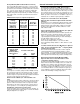
Table 4-6 20 Ton Operating Pressure Curve (All Compressors and Condenser Fans "On") COOLING CYCLE PRESSURE CURVE (Based on Indoor Airflow of 400 CFM / Ton) FULL LOAD 360 340 DISCHARGE PRESSURE, PSIG 105 F OD Ambient 320 300 95 F OD Ambient 280 85 F OD Ambient 260 75 F OD Ambient 240 220 65 F OD Ambient 200 180 160 50 55 60 65 70 75 80 85 90 95 100 SUCTION PRESSURE, PSIG To Check Operating Pressures 1. Start the unit and allow the pressures to stabilize. 2.
Table 4-6 (Continued) 30 Ton Operating Pressure Curve (All Compressors and Condenser Fans "On") COOLING CYCLE PRESSURE CURVE (Based on Indoor Airflow of 400 CFM / Ton) FULL LOAD 380 360 DISCHARGE PRESSURE, PSIG 105 F OD Ambient 340 95 F OD Ambient 320 300 85 F OD Ambient 280 260 75 F OD Ambient 240 65 F OD Ambient 220 200 180 50 55 60 65 70 75 80 85 90 95 100 SUCTION PRESSURE, PSIG To Check Operating Pressures 1. Start the unit and allow the pressures to stabilize. 2.
Table 4-6 (Continued) 50 Ton Operating Pressure Curve (All Compressors and Condenser Fans, per ckt; "On") COOLING CYCLE PRESSURE CURVE (Based on Indoor Airflow of 400 CFM / Ton) FULL LOAD 380 DISCHARGE PRESSURE, PSIG 360 105 F OD Ambient 340 320 95 F OD Ambient 300 280 85 F OD Ambient 260 75 F OD Ambient 240 220 65 F OD Ambient 200 180 50 55 60 65 70 75 80 85 90 95 100 SUCTION PRESSURE, PSIG To Check Operating Pressures 1. Start the unit and allow the pressures to stabilize. 2.
Table 4-6 (Continued) 55 Ton Hi Operating Pressure Curve (All Compressors and Condenser Fans, per ckt, "On") 55 Ton Hi Operating Pressure Curve (All Compressors and Condenser Fans, per ckt, "On") Cooling Cycle Pressure Curve (Based on Indoor Airfow of 400 CFM / Ton) Full Load 360 105 F OD Ambient 340 320 95 F OD Ambient Discharge Pressure, PSIG 300 85 F OD Ambient 280 260 75 F OD Ambient 240 65 F OD Ambient 220 200 180 50 55 60 65 70 75 80 85 90 95 100 Suction Pressure, PSIG 60 Ton Ope
Table 4-6 (Continued) 60 Ton Hi Operating Pressure Curve (All Compressors and Condenser Fans, per ckt; "On") 60 Ton Hi Operating Pressure Curve (All Compressors and Condenser Fans, per ckt, "On") Cooling Cycle Pressure Curve (Based on Indoor Airfow of 400 CFM / Ton) Full Load 105 F OD Ambient 320 300 95 F OD Ambient Discharge Pressure, PSIG 280 85 F OD Ambient 260 240 75 F OD Ambient 220 65 F OD Ambient 200 180 50 55 60 65 70 75 80 85 90 95 100 Suction Pressure, PSIG 70 Ton Standard Op
Table 4-6 (Continued) 75 Ton Standard Operating Pressure Curve (All Compressors and Condenser Fans, per ckt, "On") 75 Ton Std Operating Pressure Curve (All Compressors and Condenser Fans, per ckt, "On") Cooling Cycle Pressure Curve (Based on Indoor Airfow of 400 CFM / Ton) Full Load 380 360 105 F OD Ambient 340 Discharge Pressure, PSIG 320 95 F OD Ambient 300 280 85 F OD Ambient 260 75 F OD Ambient 240 220 65 F OD Ambient 200 180 50 55 60 65 70 75 80 85 90 95 100 Suction Pressure, PSI
Table 4-6 (Continued) 90 Ton Operating Pressure Curve (All Compressors and Condenser Fans, per ckt; "On") COOLING CYCLE PRESSURE CURVE (Based on Indoor Airflow of 400 CFM / Ton) FULL LOAD 380 DISCHARGE PRESSURE, PSIG 360 105 F OD Ambient 340 320 95 F OD Ambient 300 280 85 F OD Ambient 260 75 F OD Ambient 240 65 F OD Ambient 220 200 180 50 55 60 65 70 75 80 85 90 95 100 SUCTION PRESSURE, PSIG To Check Operating Pressures 1. Start the unit and allow the pressures to stabilize. 2.
Table 4-6 (Continued) 115 Ton Operating Pressure Curve (All Compressors and Condenser Fans, per ckt; "On") COOLING CYCLE PRESSURE CURVE (Based on Indoor Airflow of 400 CFM / Ton) FULL LOAD 380 DISCHARGE PRESSURE, PSIG 360 105 F OD Ambient 340 320 95 F OD Ambient 300 85 F OD Ambient 280 260 75 F OD Ambient 240 65 F OD Ambient 220 200 180 50 55 60 65 70 75 80 85 90 95 100 SUCTION PRESSURE, PSIG To Check Operating Pressures 1. Start the unit and allow the pressures to stabilize. 2.
Unit Start-Up (Continued) Thermostatic Expansion Valves The reliability and performance of the refrigeration system is heavily dependent upon proper expansion valve adjustment. Therefore, the importance of maintaining the proper superheat cannot be over emphasized. Accurate measurements of superheat will provide the following information. 1. How well the expansion valve is controlling the refrigerant flow. 2. The efficiency of the evaporator coil. 3.
Unit Start-Up (Continued) Damper Installation When a unit is ordered with the low ambient option (i.e., Digit 19 is a “1” in the model number), a damper is factory installed over the condenser fans 2B1, 2B4, 2B13 & 2B14 (depending on unit size). Refer to the illustration in Figure 4-1 for the damper locations. 5.
Unit Start-Up (Continued) The volume of air supplied by the combustion blower determines the amount of oxygen available for combustion, while the manifold gas pressure establishes fuel input. By measuring the percentage of carbon dioxide produced as a byproduct of combustion, the operator can estimate the amount of oxygen used and modify the air volume or the gas pressure to obtain the proper air/fuel ratio.
Table 4-7 Figure 4-7 Recommended Manifold Pressures and CO2 Levels during Furnace Operation (See Notes) Furnace MBH Firing Manifold Stage Rate %CO2 Pressure High-Fire 235 100% 8.5-9.5 3.0-3.5 Low-Fire 117 50% 6.0-7.0 0.9 High-Fire 350 100% 8.5-9.5 3.0-3.5 Low-Fire 175 50% 6.0-7.0 0.9 High-Fire 500 100% 8.5-9.5 3.0-3.5 Low-Fire 250 50% 6.0-7.0 1.25 High-Fire 850 100% 8.5-9.5 3.0-3.5 Low-Fire 500 59% 6.0-7.0 1.25 High-Fire 1000 100% 8.5-9.5 3.0-3.5 Low-Fire 500 50% 6.0-7.0 1.
Unit Start-Up (Continued) Full Modulating Gas Furnace Full Modulating gas heaters are available for the 500, 850 and 1000 MBH heater sizes. These heaters are available in the same cabinet sizes as the current heaters. The firing rate of the unit can vary from the pilot rate of 125 MBH up to the nameplate rating of the unit. The turn down ratios, therefore, vary from 4:1 for the 500 MBH to 8:1 for the 1000 MBH heater.
Unit Start-Up (Continued) 2. Follow the checkout procedures discussed in the previous steps. 10. If the measured carbon dioxide level is below the recommended values for low heat, return the burner to 90% fire rate and repeat steps 6 and 7, to achieve optimum combustion. 11. Program the burner for 100% operation and recheck the CO2 or O2 value. 12. Check the flue gas values at several intermediate output levels.
Unit Start-Up (Continued) Figure 4-10 Final Unit Checkout Typical Gas Furnace After completing all of the checkout and start-up procedures outlined in the previous sections (i.e., operating the unit in each of its Modes through all available stages of cooling and heating), perform these final checks before leaving the unit: [ ] Close the disconnect switch or circuit protector switch that provides the supply power to the unit's terminal block 1TB1 or the unit mounted disconnect switch 1S14.
Service & Maintenance Table 5-1 Control Settings and Time Delays Control Description Elec. Designation Compressor Circuit Breakers S*HF 20 - 60 S*HG 90 - 130 Combustion Airflow Switch (Gas Heat Only) High Limit Cutout (Gas Heat Only) Supply Airflow Switch (Gas Heat Only) Disch High Limit (Electric Heat Only) Linear High Limit (Electric Heat Only) Contacts Open Contacts Closed 1CB8 thru 1CB11 1CB14 thru 1CB17 See Table 5-2 See Table 5-2 See Table 5-2 See Table 5-2 4S25 see note 1 0.1 - 0.
Service & Maintenance (Continued) Table 5-3 Unit Internal Fuse Replacement Data & VFD Factory Settings 101
Service & Maintenance (Continued) Table 5-4 Filter Data Unit Model S_HF-C20 & C25 S_HF-C30 S_HF-C40 Panel-Type Filters (Note 1) Qty Size of each 12 20 X 20 X 2 16 20 X 20 X 2 16 20 X 25 X 2 Bag-Type Filters (Note 2) Qty.
Service & Maintenance (Continued) Table 5-6 Grease Recommendations Recommended Grease Exxon Unirex #2 Mobil 532 Mobil SHC #220 Texaco Premium RB Recommended Operating Range -20 F to 250 F Table 5-7 Refrigerant Coil Fin Data Model S*HF-C20 S*HF-C25 S*HF-C30 S*HF-C40 S*HF-C50 S*HF-C55 S*HF-C60 S*HF-C70 S*HF-C75 S*HG-C90 S*HG-D11 S*HG-D12 S*HG-D13 Coil Type Evaporator Hi-Cap Evaporator Condenser Evaporator Hi-Cap Evaporator Condenser Evaporator Hi-Cap Evaporator Condenser Evaporator Hi-Cap Evap
Service & Maintenance (Continued) Fan Belt Adjustment The supply fan belts and optional exhaust fan belts must be inspected periodically to assure proper unit operation. Replacement is necessary if the belts appear frayed or worn. Units with dual belts require a matched set of belts to ensure equal belt length. When removing or installing the new belts, do not stretch them over the sheaves. Loosen the belts using the belt tension adjustment bolts on the motor mounting base.
Service & Maintenance (Continued) Figure 5-1 Belt Tension Measurement and Deflection Ranges Deflection Force (Lbs.) Super Gripbelts Gripnotch Belts Cross Small P.D Section Range Min. A B 3.0 -3.6 3.8 - 4.8 5.0 - 7.0 3.4 - 4.2 4.4 - 5.6 5.8 - 8.8 Max. Min. Max 3 4 1/2 3 7/8 5 1/2 3 1/2 5 4 1/2 6 1/4 4 5 1/2 5 6 7/8 4 5 1/2 5 3/4 8 5 1/8 7 1/8 6 1/2 9 1/8 6 3/8 8 3/4 7 3/8 10 1/8 Deflection Force (Lbs.
Service & Maintenance (Continued) Table 5-8 Supply and Exhaust Fan VFD Programming Parameters Menu Parameter Description Setting 102 Motor Power Load & Motor 103 Motor Voltage Set Based on Motor Nameplate 105 106 Motor Current Set Based on Motor Nameplate Motor RPM Set Based on Motor Nameplate Description Set only for applications using 3hp HiEfficiency motors. Set to 2.2 kW.
(q) Press the Up Arrow button to scroll to the Active Setup menu. (r) Press the Change Data button. (s) Press the Up Arrow button to scroll to the Setup 1 setting. (t) Press the OK button. (v) Press the Change Data button. (w) Press the Up Arrow button to scroll to the Down load All Parameters setting. (x) Press the OK button Note: Item 5 resets the drive to the default factory settings. The program parameters listed in Table 58 will need to be verified or changed as described in Item 3 and 4.
Service & Maintenance (Continued) [ ] Check the condition of the gasket around the control panel doors. These gaskets must fit correctly and be in good condition to prevent water leakage. After greasing the bearings, check the setscrews to ensure that the shaft is held securely. Make sure that all bearing braces are tight. [ ] Verify that all wire terminal connections are tight. [ ] Remove any corrosion present on the exterior surfaces of the unit and repaint these areas.
Service & Maintenance (Continued) Note: Refrigerant oil is detrimental to some roofing materials. Care must be taken to protect the roof from oil leaks or spills. CAUTION Coil Cleaners! Coil cleaners can damage roofs, surrounding buildings, vehicles, etc. Cleaning substances should be checked to ensure that they will not cause damage to surroundings. Coils and roof (if applicable) should berinsed thoroughly. Do not spray coil cleaners in windy conditions.
Service & Maintenance (Continued) Final Process Complete Unit Model Number: For future reference, you may find it helpful to record the unit data in the blanks provided. Unit Serial Number: Unit "DL" Number ("Design special" units only): Wiring Diagram Numbers (from unit control panel): —schematic(s) —connections Unit Address (TCI) Network ID (LCI) Table 5-8 Sample Operator's Maintenance Log (See Note) Refrigerant Circuit #1 Refrigerant Circuit #2 Current Ambient Compr. Suct. Disch.
Index A D AC Conductors ................................................................. 45 See Table 3-8 Adjusting the Fresh Air Damper ...................................... 80 Airflow Measurements ..................................................... 63 Damper Adjustment ........................................................... 93 See Low Ambient Dampers Damper Installation ............................................................ 94 See Low Ambient Dampers Daytime Warm-up ......................
See Figure 3-11 Flue Gas Carbon Dioxide & Oxygen Measurements ..... 96 See Figure 4-7 Freeze Protection .............................................................. 58 Freezestat .......................................................................... 10 Fresh Air & Return Air Damper ................................... 80-81 See Figure 4-5: Table 4-5 Frostat Control ................................................................... 55 Fuse replacement data ..............................................
Return Air Humidity Sensor (3U64) .................................. 8 return air temperature reaches 135 F ............................. 10 Rooftop Module ................................................................... 7 RTM Resistance Input vs Setpoint Temperatures ............. 7 RTM Resistance Value vs System Operating Mode .......... 7 S Sample Model Number .................................................... 4–5 Sample Operator's Maintenance Log ..............................
WARRANTY AND LIABILITY CLAUSE COMMERCIAL EQUIPMENT RATED 20 TONS AND LARGER AND RELATED ACCESSORIES PRODUCTS COVERED - This warranty* is extended by American Standard Inc. and applies only to commercial equipment rated 20 Tons and larger and related accessories.
115
116