
Instruction Manual

98
Unit Start-Up (Continued)
10. If the measured carbon dioxide level is below the rec-
ommended values for low heat, return the burner to 90%
fire rate and repeat steps 6 and 7, to achieve optimum
combustion.
11. Program the burner for 100% operation and recheck the
CO
2
or O
2
value.
12. Check the flue gas values at several intermediate out-
put levels. If corrections are necessary;
- Adjust the pressure ratio screw 1 at high fire operation
only.
- Adjust the bias screw 2 at low fire operation only.
13. Press the STOP key at the Human Interface Module in
the unit control panel to stop the system operation.
Limited Modulating Gas Furnace
Limited Modulating gas heaters are available for the 500,
850 and 1000 MBH heater sizes. These heaters are avail-
able in the same cabinet sizes as the current heaters.
The firing rate of the unit can vary from 33% rated MBH up
to the nameplate rating of the unit. The turn down ratios,
therefore, is limited to 3:1.
Heat Exchanger
The heat exchanger drum, tubes and front and rear head-
ers utilities the same materials as the standard two stage
furnace.
Unit control
The unit is controlled by a supply air temperature sensor lo-
cated in the supply air stream for VAV units. CV units have
two sensors, one located in the supply air stream and the
zone sensor. The temperature sensor signal is sent to the
Heat module of the Intellipak
®
Unit Control. The control sig-
nal from the Heat Module is an inverse proportional 5 -10V
DC. The higher the voltage signal, the lower the call for
heat.
The 5 -10V DC. signal controls the angular position of the
combustion air damper through a direct coupled damper ac-
tuator motor. The position of the air damper in turn controls
the combustion air pressure that is sensed by the modulat-
ing gas valve. The greater the combustion air pressure, the
greater the call for gas and the higher the firing rate of the
heater. As the temperature setpoint is reached, the Modu-
lating Heat control will cause the combustion air actuator to
change the damper position to a lower firing rate that
matches the heat load of the space.
1. To verify and check system optimum combustion, use
Table 4-1 to program the limited modulating heat system
components for 90% operation by scrolling through the
Human Interface displays.
2. Follow the checkout procedures discussed in the previ-
ous steps.
Note: The minimum firing rate for a limited
modulating gas furnace in step 8 is 33%. Travel of
the combustion air damper is limited by a welded
stop.
3. Press the STOP key at the Human Interface Module in
the unit control panel to stop the system operation.
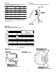
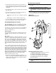
Figure 4-9
Modulating Gas Regulator
Modulating Gas Regulator Legend
1. Adjustment and indication of the air to gas ratio.
2. Adjustment and indication of the bias.
3. Connection for the Ambient compensation line.
4. Connection for the gas pressure sensing line.
5. Connection for the air pressure sensing line.
6. Stroke indication.
Note: There are no serviceable parts on the SKP70
actuator. Should it become inoperative, replace the
actuator.