
Instruction Manual

57
Unit Start-Up (Continued)
eration. As you review the sequence of operations, keep the
following in mind:
1. The furnace will not light unless the manual gas valves
are open and the control circuit switch 4S24 is closed.
2. The control systems are wired to ensure that heating and
cooling cannot occur simultaneously.
3. The unit supply fans must run continuously so air flow
switch 4S38 will stay closed.
4. Modulating Gas heat is available during both occupied
and unoccupied operation.
Whenever there is a call for heat, 1U50-K1 energizes and
combustion blower motor 4B11 begins to operate at High
speed on the 850 and 1000 MBH heaters. The blower will
operate on low speed for the 500 MBH. A relay 4K119 in
parallel with the main gas valve actuator control output, in-
sures the actuator will be open prior to proof of flame. This
will force the combustion air actuator 4U82 to the open po-
sition, causing the auxiliary switch on 4U82 to close. This
insures complete purging of the combustion chamber during
the 60 second purge cycle.
Ignition control IC board 4U18 will not energize, however,
unless the supply air flow switch 4S38, combustion air flow
switch 4S25, high limit cutout 4S26, the auxiliary switch on
combustion air actuator 4U82 and the proof of closure
switch on gas valve 4L22 are closed. These are all part of
the safety interlock system.
With all these conditions satisfied, the IC board energizes
and initiates an internal 60 second pre-purge time delay.
When the pre-purge period expires, 4U18 energizes both
the ignition transformer 4T7 and solenoid 4L9 on the inter-
mittent pilot valve. At that point, 4U18 gives electrode 4E1
approximately 10 seconds to establish a pilot flame. (The
presence of this flame is proven by flame rod 4U19.)
If 4U18 does not detect a pilot flame at the end of this pe-
riod, it will shut down and lock out the ignition / combustion
circuit.
If the pilot is ignited within 10 seconds, the IC board de-en-
ergizes the ignition transformer 4T7 and electrode 4E1. At
this point, relay 4K119 will energize, starting the combus-
tion air actuator and the furnace. The feedback signal from
the discharge temperature sensor will cause the modulating
output from the heat module to change the damper position
as required to maintain the outlet temperature within the de-
sired band.
Flame Failure
In the event that IC board 4U18 loses the “proof-of-flame”
input signal during furnace operation, it will make one at-
tempt at reignite. If a flame is not reestablished within the
10 second trial period, 4U18 will shut down and lock out the
ignition /combustion control circuit. (Combustion blower mo-
tor 4B11 continues to run as long as a heating requirement
exists and control circuit switch 4S24 is ON.)
Once locked out on flame failure, the IC board will not reac-
tivate the ignition/combustion control circuit until it is reset
manually. To do this, press the reset button on the front of
the IC board case.
The system will operate in the low heat mode until there is
an additional call for heat is established by closing the K3
contacts on the Heat Module.
On Variable Air Volume systems, the sequencing time delay
relay (4DL6) will energize the combustion blower motor re-
lay (4K33) which switches the combustion blower motor to
high speed and energizes the 2nd stage solenoid on the
gas valve (4L7) after approximately 60 seconds.
If the flame rod (4U19) does not detect a pilot flame within
the 10 second trial for ignition period, the control will lock-
out. If a flame failure occurs during operation, the gas valve
(4L7), the sequencing time delay relay (4DL6), and the
combustion blower relay (4K33) is de-energized. The sys-
tem will purge and attempt to relight the pilot. If a flame is
not detected after this attempt, the Honeywell ignition con-
trol (4U18) will lock out. The combustion blower motor will
continue to operate as long as a heating demand exists and
the system switch (4S24) is "On".
Once the heating demand has been satisfied, the combus-
tion blower and the Honeywell ignition control board (4U18)
is de-energized.
Propane Gas
Units that operate on propane gas after 1990 have two (2)
additional controls that affect the combustion blower motor
operation and the sequence of the gas valve operation.
With the post purge time delay relay (4DL4), the additional
service switch (4S24), and the additional 115 volt control re-
lay (4K31) installed, the sequence of operation is as fol-
lows:
Power is applied to the Honeywell ignition control board
(4U18) through the high limit switch (4S26). The Honeywell
ignition control board (4U18) will sequence through its pre-
purge timing and pilot ignition sequence to The post purge
time delay relay (4DL4) delays the starting of the combus-
tion blower motor by approximately 60 seconds. Once the
timing has elasped, the combustion blower motor will start,
closing the combustion air switch (4S25).
Energize the control relay (4K31) and the sequence time
delay relay (4DL6). 24 volts is applied from the new service
switch (4S24) through the normally open control relay
(4K31) contacts to energize the 1st stage solenoid on the
gas valve (4L7).
On an additional call for heat, the K3 contacts on the Heat
Module will close to energize the combustion blower relay
(4K33) which switches the combustion blower motor to high
speed and closes its normally open contacts allowing 24
volts to energize the 2nd stage on the gas valve (4L7).
Once the heating demand has been satisfied, the
Honeywell ignition control board (4U18) and the post purge
time delay relay (4DL4) is de-energized. The combustion
blower motor will continue to operate for approximately 15
seconds to purge the heat exchanger on the "Off" cycle.
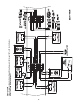
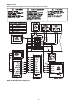
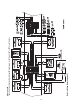
Modulating Gas Sequence of Operation
Full and Limited Modulating Gas Furnace
The control system for the rooftop units are wired to ensure
that the heating and cooling do not occur simultaneously.
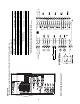
Refer to the modulating heat wiring diagram that shipped
with the unit while reviewing the following sequence of op-