
Instruction Manual

64
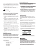
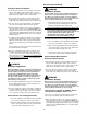
Figure 4-1
Condenser Fan Location with Human Interface Designator
5. Use Table 4-1 to program the Supply Fan for operation
by scrolling through the displays.
6. Once the configuration for the Fan is complete, press the
NEXT key until the LCD displays the “Start test in
__Sec.” screen. Press the + key to designate the delay
before the test is to start.
This service test will begin after
the TEST START key is pressed and the delay desig-
nated in this step has elapsed. Press the ENTER key to
confirm this choice.
WARNING
Live Electrical Components!
During installation, testing, servicing and troubleshoot-
ing of this product, it may be necessary to work with live
electrical components. Have a qualified licensed electri-
cian or other individual who has been properly trained in
handling live electrical components perform these
tasks. Failure to follow all electrical safety precautions
when exposed to live electrical components could result
in death or serious injury.
7. Press the TEST START key to start the test. Remember
that the delay designated in step 6 must elapse before
the fans will begin to operate.
8. With the system in the SERVICE MODE and the supply
fan rotating in the proper direction, measure the amper-
age at the supply fan contactor 1K16 & 1K15 (additional
contactor for 90 thru 130 Ton units). If the amperage ex-
ceeds the motor nameplate value, the static pressure is
less than design and the airflow is too high. If the amper-
age is below the motor nameplate value, static pressure
may be too high and CFM may be too low. To determine
the actual CFM (± 5%);
a. Measure the actual fan RPM
b. Calculate the Theoretical BHP
Actual Motor Amps X Motor HP)
Motor Nameplate Amps
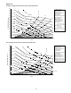
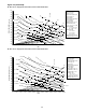
c. Plot this data onto the appropriate Fan Performance
Curve in Figure 4-2. Where the two points intersect,
read straight down to the CFM line.