
Installation and Maintenance Manual


SCXG-SVX01H-EN 13
Pre-Installation Considerations
Receiving
Receiving Checklist
Complete the following checklist immediately after
receiving unit shipment to detect possible shipping
damage.
• Inspect individual cartons before accepting. Check for
rattles, bent carton corners, or other visible indications
of shipping damage.
• If a unit appears damaged, inspect it immediately
before accepting the shipment. Make specific
notations concerning the damage on the freight bill.
Do not refuse delivery.
• Inspect the unit for concealed damage before it is
stored and as soon as possible after delivery. Report
concealed damage to the freight line within the allotted
time after delivery. Check with the carrier for their
allotted time to submit a claim.
• Do not move damaged material from the receiving
location. It is the receiver’s responsibility to provide
reasonable evidence that concealed damage did not
occur after delivery.
• Do not continue unpacking the shipment if it appears
damaged. Retain all internal packing, cartons, and
crate.Take photos of damaged material if possible.
• Notify the carrier’s terminal of the damage
immediately by phone and mail. Request an
immediate joint inspection of the damage by the
carrier and consignee.
Notify yourTrane representative of the damage and
arrange for repair. Have the carrier inspect the damage
before making any repairs to the unit.
Ship-Separate Accessories
Field-installed sensors ship separately inside unit’s main
control panel. Extra filters, sheaves, and belts ship in unit’s
fan motor section. Condenser plugs, spring isolators, and
isopads ship in unit’s bottom left side.
Contractor Installation
Responsibilities
Complete the following checklist before beginning final
unit installation.
• Verify the unit size and tagging with the unit
nameplate.
• Make certain the floor or foundation is level, solid, and
sufficient to support the unit and accessory weights.
Level or repair the floor before positioning the unit if
necessary.
• Allow minimum recommended clearances for routine
maintenance and service. Allow space at end of the
unit for shaft removal and servicing. Refer to unit
submittals for dimensions. See also
“Service
Clearances,” p. 24.
• Allow three fan diameters above the unit for the
discharge ductwork. Return air enters the rear of the
unit and conditioned supply air discharges through the
top.
• Electrical connection knockouts are on the top, left side
of the unit.
• Allow adequate space for piping access and panel
removal. Condenser water piping, refrigerant piping,
and condensate drain connections are on the lower left
end panel.
Note: Unit height and connection locations will change if
using vibration isolators. The unit height may
increase up to 5 7/8” with spring type isolators.
• Electrical supply power must meet specific balance
and voltage requirements as described in section
“Installation - Electrical,” p. 39.
• Water-cooled units only:The installer is responsible for
providing a condenser main, standby water pump,
cooling tower, pressure gauges, strainers, and all
components for waterside piping. See
“Water Piping,”
p. 32 for general waterside recommendations.
• Air-cooled units only:The installer is responsible for
providing and installing the remote air-cooled
condenser and refrigerant piping.
Unpackaging
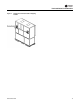
Commercial self-contained units ship assembled with
protective coverings over the coil and discharge openings.
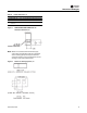
Figure 2, p. 14 illustrates a typical shipping package.
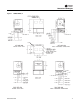
Unit Protective Covers
Remove the shipping protection coverings from the
human interface panel (HI) at the control panel, the filter
box (or air inlet opening), the discharge air opening, and
optional variable frequency drive (VFD).
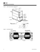
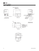
Supply Fan Isolators
Remove the shipping channels and mounting bolts from
beneath the fan. See Figure 4, p. 15. Open both fan
compartment access doors to access the channels.There
are four mounting points for 20-38 ton units.
Note: For 20-38 ton units, do not remove the fan
assembly shipping blocks and tie down bolts if the
fan speed is 750 rpm or less.
While keeping the fan mounting frame level, turn the fan
isolator height adjusting bolts until the fan housing P-
gasket compresses 1/4” against the roof transition piece.
See Figure 4, p. 15.