
Installation and Maintenance Manual


Operating Principals
SCXG-SVX01H-EN 67
circuit frost protection can override the “minimum” timer
and reduce the five minute minimum required time
period.
When the unit is powered up, or manually reset there will
be a three to eight minute delay before the first
compressor may be turned on as requested by the unit
temperature control algorithm.
Compressor Lead/Lag Operation
Compressor lead/lag is a user-selectable feature at the HI
panel and is available on all units. After each request for
compressor operation, the lead refrigeration circuit or
compressor switches, thereby causing a more equitable or
balanced run time among compressors.
When lead/lag is enabled, each time the system cycles, it
will alternate between the standard compressor staging
and the lead/lag staging. Using Table 40, p. 67, a SXWG
30-ton unit will first stage compressor B then A, then AB
for first cycle and A, then AB for the second cycle.
Appropriate condenser valves (water-cooled and
condenser fans (air-cooled) will stage with appropriate
compressors to maintain saturated condensing
temperature. Enabling lead/lag may drop a cooling stage
when compared to standard staging. See Table 40, p. 67
for compressor staging.
Step Control
Steps of mechanical cooling are control based on supply
air or zone temperature. See Table 40, p. 67 for
compressor staging.
Capacity is based on an integrating control concept.The
unit capacity matches the existing load and maintains an
average supply air temperature within the supply air
setpoint temperature control band region.
The supply air temperature control band is centered
around supply air temperature setpoint and is adjustable
from 2 to 12°F. In a steady state, the unit will either
maintain a constant level of cooling capacity with the
supply air temperature within the control band, or the
highest active cooling level will cycle to provide an
average supply air temperature equal to the setpoint.
If the supply air temperature swings outside the limits of
the control band, the mechanical cooling capacity will
increase or decrease by one level accordingly.The change
occurs by integrating the temperature offset from the
control band limit.
A minimum time delay of five minutes follows each
change in cooling level.This time delay promotes stability
by allowing the system to respond to the change before
any further control action occurs. As the supply air
temperature approaches setpoint, the time duration
between changing levels of cooling capacity increases.
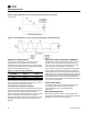
See Figure 56, p. 68 for the typical unit operating curve.
Figure 57, p. 68 shows typical unit performance when
supply air temperature swings exceed the control band
limits.
Adjust the supply air temperature control band according
to the desired unit performance. Increasing the control
band reduces the equipment cycle rate and increases the
maximum potential supply air temperature deviation from
setpoint. Conversely, decreasing the control band reduces
the maximum potential temperature deviation, but
increases the compressor cycle rate.
Follow these recommendations concerning the supply air
temperature control band settings based on expected unit
sizing:
2 Cooling stage unit: 9°F
3 Cooling stage unit: 7°F
4 Cooling stage unit: 6°F
Table 40. Compressor stages.
Unit Size
Refrigerant
Circuit Type
Model # Digit 5
Compressor HP
by Stage
Standard
Compressor
Staging
Lead/Lag
Compressor
Staging
SCM
or
MCMAB
SXWG 20, 25
SXRG 20
Independent 10 10 B/AB A/AB MCM
SXWG 30
SXRG 25
Independent 15 10 B/A/AB A/AB MCM
SXWG 35
SXRG 32
Independent 15 15 B/AB A/AB MCM