
Installation and Maintenance Manual


Operating Principals
SCXG-SVX01H-EN 69
Water Purge
This user-definable feature allows the user to select a
purge schedule to automatically circulate water through
the economizer and condensers periodically during non-
operational times.This allows fresh chemicals to circulate
in waterside heat exchangers.This feature is on all units
and is defined at the HI.
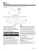
Water Piping Options
Water piping is factory-installed with left-hand
connections on units without a waterside economizer.
Units can be ordered with either basic piping or
intermediate piping. Also, units with waterside
economizers can be set for either variable or constant
water flow at the HI. SeeFigure 58, p. 70 and Figure 59,
p. 70 for detailed piping configuration information.
With compatible piping configurations, the unit can be
configured to provide:
1. Constant water flow with basic or intermediate piping
or
2. Variable water flow (head pressure control) with
intermediate piping only.
Constant water flow is for condenser pumping systems
that are not capable of unloading the water-pumping
system. Variable water flow maximizes energy saving by
unloading the water pumping system.
Basic Water Piping
This option is available on units without a waterside
economizer and with condenser water applications above
54°F (12.2°C) that do not require condensing pressure
control. Left hand water connections and piping are
extended to the unit exterior. Manifold piping is factory
installed.
Intermediate Water Piping
This option provides condensing temperature control
when the unit is configured (user defined at the HI) for
variable water flow with or without a waterside
economizer. A two-way modulating control valve is wired
and installed in the unit to maintains a specific range of
water temperature rise through the condenser when
entering fluid temperature is less than 58°F (15°C).This
option allows the compressor to operate with entering
fluid temperature down to 35°F (2°C).The minimum valve
position to maintain minimum condenser flow rates is
user-defined at the HI.This valve drives closed if the unit
shuts down or if a power failure occurs.
Water Flow Switch Option
A water flow switch is factory installed in the condenser
water pipe within the unit. Whenever the flow switch
detects a water flow loss prior to or during mechanical
cooling, compressor operation locks out and a diagnostic
code displays. If water flow is restored, the compressor
operation automatically restores.
Water-Cooled Condensers
Units that are set up for variable water flow will modulate
a water valve to maintain a user-defined condensing
temperature setpoint. Condensing temperature will be
referenced utilizing factory installed sensors located at
each condenser.
Waterside Economizer Option
The waterside economizer option takes advantage of
cooling tower water to either precool the entering air to aid
the mechanical cooling process or, if the water
temperature is low enough, provide total system cooling.
Waterside economizing enables when the unit’s entering
water temperature is below the unit’s entering mixed air
temperature by a minimum of 4°F plus the economizer’s
approach temperature.The approach temperature default
is 4°F. Waterside economizing disables when the unit’s
entering water temperature is not below the unit’s
entering mixed air temperature by at least the water
economizer approach temperature.The approach
temperature defaults to 4°F.The economizer acts as the
first stage of cooling. If the economizer is unable to
maintain the supply air setpoint, the unit control module
brings on compressors as required to meet the setpoint.
The waterside economizer includes a coil, modulating
valves, controls, and piping with cleanouts.The coil
construction is ½-inch (13 mm) OD seamless copper tubes
expanded into aluminum fins.The evaporator and
economizer coils share a common sloped (IAQ) drain pan.
Drain pan options are either galvanized or stainless steel,
and are insulated and internally trapped.
The waterside economizer coil is available with either a
two or four row coil, with no more than 12 fins per inch.
The tubes are arranged in a staggered pattern to maximize
heat transfer.The coil has round copper supply and return
headers with removable cleanout and vent plugs.The
optional mechanical cleanable economizer has removable
cast iron headers to allow easy mechanical cleaning of the
tubes.The waterside working pressure is rated for 400
psig (2758 kPa).
NOTICE:
Proper WaterTreatment!
The use of untreated or improperly treated water could
result in scaling, erosion, corrosion, algae or slime. It is
recommended that the services of a qualified water
treatment specialist be engaged to determine what
water treatment, if any, is required. Trane assumes no
responsibility for equipment failures which result from
untreated or improperly treated water, or saline or
brackish water.
Table 42. Condenser water piping connection sizes
Unit Size Inlet Pipe Outlet Pipe
SXWG 20, 25, 30, 32, 35 2 1/2 NPT 2 1/2 NPT