
Installation and Maintenance Manual
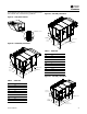
Table Of Contents
- Introduction
- Model Number Descriptions
- General Information
- Overview of Manual
- Model Number Description
- Unit Nameplate
- Compressor Nameplate
- Unit Description
- Indoor Fan Failure Input
- Low Pressure Control ReliaTel Control
- Refrigerant Circuits
- High Pressure Control ReliaTel Control
- Space Temperature / RH Sensor (Optional)
- High Temperature Sensor
- Outdoor Air Temperature and Relative Humidity Sensor
- Control Input (Occupied / Unoccupied)
- Hot Gas Reheat
- 100 Percent Outdoor Air Hood with Damper and Filters
- Modulating Indirect Gas-Fired Burner
- Through the Base Electrical with Disconnect Switch
- Through the Base Gas Piping
- Hinged Access Doors
- Modulating Electric Heat
- Unit Inspection
- Unit Clearances, Curb Dimensions, and Dimensional Data
- Unit Weight and Rigging
- Sequence of Operation
- Installation
- System Configuration and Pre-Start
- Start-Up
- Maintenance
- Performance Data
- Alarms and Troubleshooting
- Appendix
Installation
OAU-SVX01E-EN 27
ensure that the unit’s supply power wiring is properly sized
and installed, refer to the following guidelines.
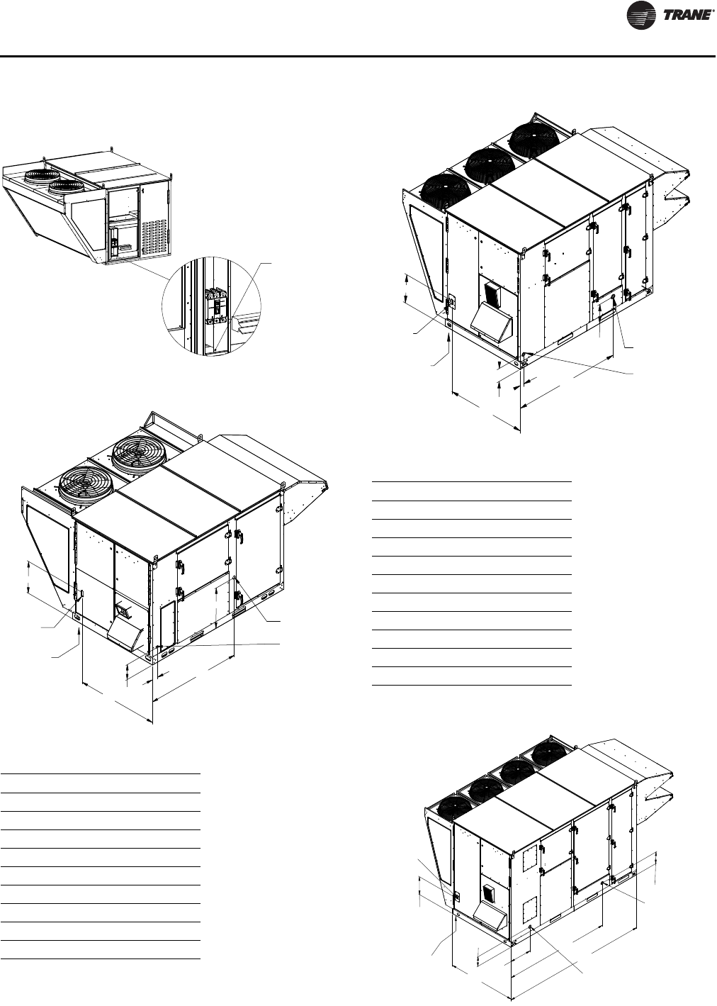
Figure 27. Main power entrance
Figure 28. OA1D utility connections
Table 4. OA1D Unit
MBh Pipe Connection (in.)
50 1/2
75 1/2
100 1/2
125 1/2
150 3/4
200 3/4
250 3/4
300 3/4
350 1
MAIN POWER ENTRANCE
FOR UNIT
3/4" NPT
CONDENSATE DRAINELECTRICAL
DISCONNECT
THROUGH BASE
ELECTRIC
18.13
54.26
23.37
8.74
3.21
46.58
GAS INLET
NPT SIZE VARIES
Figure 29. OA2 utility connections
Table 5. OA2D Unit
MBh Pipe Connection (in.)
150 3/4
200 3/4
250 3/4
300 3/4
350 1
400 1
500 1
600 1-1/4
700 1-1/4
800 1-1/4
Figure 30. OA3 utility connections
ELECTRIC
THROUGH BASE
DISCONNECT
ELECTRICAL
1" NPT
CONDENSATE DRAIN
GAS INLET
NPT SIZE VARIES
74.04
13.33
54.49
9.09
2.50
18.95
THROUGH
THE BASE
ELECTRIC
GAS INLET
NPT SIZE VARIES
1-1/4" NPT
CONDENSATE DRAIN
ELECTRICAL
DISCONNECT
9.76
21.56
104.33
144.00
67.00
17.74
11.78