Installation, Operation, and Maintenance Packaged Terminal Air Conditioner PTEE070/PTHE070 (7,000 Btuh) PTEE090/PTHE 090 (9,000 Btuh) PTEE120/PTHE120 (12,000 Btuh) PTEE150/PTHE150 (15,000 Btuh) September 2006 PTAC-SVX01C-EN
Table of Contents Table of Contents . . . . . . . . . . . . . . . . . . . . . . . . . . . . . . . . .2 Model Number Description . . . . . . . . . . . . . . . . . . . . . . . . .3 General Information . . . . . . . . . . . . . . . . . . . . . . . . . . . . . . .4 Pre-Installation . . . . . . . . . . . . . . . . . . . . . . . . . . . . . . . . . . .6 Table 1. Minimum interior and exterior projections . . . . . . . .6 Table 2. Minimum clearances and projections . . . . . . . . . . .7 Receiving and Handling . .
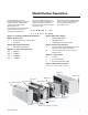
Model Number Description Each Packaged Terminal Air Conditioner/Heat Pump is assigned a multiple-character alphanumeric model number that precisely identifies each unit. The model number helps owner/ operator, installing contractors, and service technicians to define the operation, components and options for a specific unit. An explanation of the identification code that appears on the unit nameplate is shown below.
General Information NOTICE: Warnings and Cautions appear in appropriate sections throughout this manual. Read these carefully. WARNING Indicates a potentially hazardous situation which, if not avoided, could result in death or serious injury. CAUTION Indicates a potentially hazardous situation which, if not avoided, may result in minor or moderate injury. It may also be used to alert against unsafe practices.
General Information Refrigerant Handling Procedures WARNING Contains Refrigerant! System contains oil and refrigerant under high pressure. Recover refrigerant to relieve pressure before opening the system. See unit nameplate for refrigerant type. Do not use non-approved refrigerants, refrigerant substitutes, or refrigerant additives.
Pre-Installation Pre-Installation Under these circumstances, careful jobsite analysis and cautions are required. Consult your local HVAC representative before attempting such installations. Pre-Installation Considerations Before beginning installation, make the following considerations: 1. 2. Verify the wall opening is in the correct location and the correct size.
Pre-Installation Table 2. Minimum clearances and projections Option In. Mm In. Mm Minimum clearances A In. Mm Minimum projection B C Wall sleeve only 3 75 0 0 0 0 Subbase kit 3 75 3 1/4 85 2 3/4 70 Leveling legs kit 3 75 3 75 Hydronic heat kit(1) 9 230 2-6”(2) 50 -150(3) 2 3-3 1/8(4) 50 76-80(5) Drain kit 3 75 0(6) 1(7) 0 0 Hardwire kit 3 75 3 75 0 0 (1) (2) (3) (4) (5) (6) (7) Max height is based on skirt options available.
Unit Dimensions Unit Dimensions Figure 4. Unit with wall sleeve and subbase accessory Figure 5.
Unit Dimensions PTAC Wall Sleeve Unit controls compartment Air discharge Figure 6. Top view of the hydronic kit Hotwater or steam inlet and outlet connection (left hand coil connection) Steam inlet and outlet connection (right hand coil connection) Steam/water coil position 53-2/3” 1“ 1-1/20” 20-1/4” PTAC 16-1/5” Front View Air inlet Figure 7. Hydronic kit front view Hydronic front 1-3/8” - 1-1/2” Top of wall sleeve 5.00” 12.62 Bottom of wall sleeve Figure 8. Toe plate 0 to 3.
Installation Installation WARNING Live Electrical Components! During installation, testing, servicing and troubleshooting of this product, it may be necessary to work with live electrical components. Have a qualified licensed electrician or other individual who has been properly trained in handling live electrical components perform these tasks. Failure to follow all electrical safety precautions when exposed to live electrical components could result in death or serious injury.
Installation Table 3. Electric heat capacity and electrical data, models PTEE and PTHE(i) Voltage(ii) Electric heater # of Size (kW) stages Nominal heating Building circuit requirement Btu/h at Btu/h at Total 230/208V 265V watts(iii) Unit total amps Maximum Minimum ampacity(iv) protection(v) Plug 230/208 2.0/1.6 1 6,800/ 5,500 - 2000/ 1600 8.9/7.9 11.4 15 6 - 15 P 230/208 3.0/2.4 1 10,200/ 8,200 - 3000/ 2400 13.4/11.8 17 20 6 - 20 P 230/208 5.0/4.
Installation Figure 9. Panel wall installation Installation Procedure WARNING Hazardous Voltage w/ Capacitors! 4. Install wall sleeve in wall opening. Step 1. Remove rear closure panel from wall sleeve. 5. Install unit chassis in wall sleeve. 1. Disconnect all electric power, including remote disconnects before servicing. Follow proper lockout/ tagout procedures to ensure the power cannot be inadvertently energized.
Installation 2. Grasping the top and bottom flanges of the rear closure panel as shown in Figure 12, the entire panel is pulled out diagonally from one side. Step 4. Install wall sleeve in wall opening. For condensate to drain properly inside the unit, the sleeve must be installed properly: • level from right to left • with a slight downward pitch from the indoor side to the outdoor side Note: Figure 12. Pull rear closure panel out of wall sleeve Note: Step 2. Install drain kit in wall sleeve.
Installation Table 5. Unit power supply Voltage Options Accessory Accessory part number Required: Universal Power Cord 15 Amp BAYPCRD007 115V Option 1. A field supplied 115 volt 15 amp receptacle is mounted in the building floor or wall. A Trane 115 volt 15 amp power cord BAYPCRD007 is connected to the PTAC and plugged into the receptacle. Option 2. Required: Universal Power Cord 15 Amp BAYPCRD007 Universal Subbase BAYSUB001 A Trane subbase BAYSUB001 is attached to the wall sleeve.
Installation Note: Note: Table 6. If using a third party thermostat to control the unit, the thermostat must have a clearly marked OFF state or position. Table 7. Wiring Voltage Voltage at terminal Unit It is important to make sure that the control board’s fuse is functioning. The specs for the control board fuse are: 5x20mm, 250V, 315mA, fast acting. For more inormation on a blown fuse on the control board, check the Troubleshooting section of this document.
Installation Table 8.
Installation Step 9. Programmable Settings The controller has a total of six (7) parameters that are userconfigurable: Table 9. Set point configuration Configuration Configuration step Step description setting Setting description 1 Ventilation is disabled Ventilation Enable 0 1 (default) 1. Vent Door Configuration 2. Indoor Fan Cycle configuration 3. Temperature Setpoint Limiting configuration 4. Energy Management Setpoint Offset configuration 5. Display Units configuration 6.
Installation 1. Ventilation Door Function The power door works based upon control logic functions. When the unit is on, the vent door will open to allow fresh air to be conditioned before entering the room. When the unit is off, the door closes to prevent unconditioned air from entering the room. For more information on vent door function with dehumidificaiton, refer to the dehumidification chart. 2.
Installation Table 12. Indoor fan cycle configuration Config # Indoor Fan Cycle Mode Indoor fan will not run when the user mode is OFF. (DEFAULT) Indoor fan will cycle to the user selected speed in conjunction with the compressor or electric heat during HEAT or COOL 0 Indoor fan will run continuously at the user selected fan speed during FAN EMS has no affect. Indoor fan will normally run continuously at the user selected fan speed. Indoor fan will not run when the user mode is OFF.
Installation Table 14. PTEE manual test sequence Indoor Indoor Remote Fan High Fan Low Fan Step Outdoor Condensate Fan Pump Comp Reversing Ventilation Valve Aux.
Operation Sequence of Operation Automatic 3-minute Compressor Lockout After the compressor cycles off, it will not restart for three minutes. This feature prevents the compressor from short cycling and extends the overall life. Automatic 2nd Stage Electric Heat (PTHE only) If the room temperature falls to 2.5°F below the setpoint temperature or the unit compressor fails, the reverse cycle heat is shut off and the electric heat is turned on.
Operation Table 16. Input User inputs Function TB1 + Remote display communications link (+) - Remote display communications link (-) TB2 EN Energy management system input VT Ventilation input O Reversing valve (class 2 thermostat) GL Low fan speed (class 2 thermostat) GH High speed fan (class 2 thermostat) Y Cool (class 2 thermostat) W Heat (class 2 thermostat) R 24VAC common1 C Ground2 RF Remote fan relay output Notes: 1.
Operation Table 17. Air conditioner performance data PTEE 07 PTEE 09 115 208 230 265 Cooling capacity (Btu/H) 7,200 6,800 7,000 Cooling amps (A) 5.3 2.9 EER (Btu/H/ watt) 12.2 Moisture removal (Pts/h) 115 PTEE 12 208 230 PTEE 15 208 230 265 115 7,300 9,300 8,800 9,000 8,700 12,000 11,600 11,800 11,800 13,700 13,900 14,400 2.7 2.4 7.3 3.9 3.6 3.1 9.7 5.1 4.8 4.1 6.9 6.4 5.7 12.0 12.0 12.0 11.5 11.4 11.4 11.3 11.2 11.2 11.2 11.3 10.0 10.0 9.8 1.8 2.
Operation Table 18. Heat pump performance PTHE 07 Voltage (V) 208 230 PTHE 09 265 208 230 PTHE 12 PTHE 15 265 208 230 265 208 230 265 Cooling data Cooling capacity(Btu/H) 7,200 7,400 7,200 8,900 9,100 8,700 11,700 12,000 11,700 13,300 13,600 13,600 Cooling amps (A) 2.9 2.7 2.3 3.9 3.7 3.1 5.1 4.8 4.2 6.8 6.3 5.5 12.0 12.0 11.4 11.4 10.8 11.2 11.2 11.0 9.9 9.9 9.9 2.1 2.1 2.5 2.6 2.6 3.0 3.1 3.1 4.1 4.1 4.
Operation Table 19. Cooling temperature change - air conditioners PTEE0701 Room air dry bulb 90 85 80 75 70 Table 20.
Operation Table 20. Cooling temperature change - heat pumps (continued) PTHE0701 Room airdry bulb Temperature across indoor coil (∆ T) Room air wet bulb 75 70 Table 21.
Operation Table 23.
Operation Table 25. Unit accessory model numbers Description Table 25.
Operation Table 26.
Maintenance Maintenance Procedures Wall Sleeve Intake Air Filter Perform the following maintenance procedures to ensure proper unit operation. Clean the wall sleeve every four months or more often as the atmospheric conditions require. WARNING Live Electrical Components! Remove any debris from the bottom of the panel, and from around any internal or external drain kit accessory item prior to using water or detergent. This will ensure that no debris clogs up the drain holes.
Maintenance 5. Reinstall the filter by reattaching the hook to the bottom of the vent door and replacing the two screws, slide the chassis back into the wall sleeve, secure it in place with six screws and reinstall the front cabinet. • Vent door If the unit is installed ocean side or in a corrosive atmosphere, its life may be greatly reduced by the corrosive environment. Under these conditions the unit should be removed from the sleeve and completely cleaned at least four times per year.
Maintenance Leak Testing Refrigerant leaks are best detected with a halide or electronic leak detector. WARNING Use of Pressure Regulator – Valves – Gauges! Always use pressure regulators, valves, and gauges to control drum and line pressures when pressure testing equipment. Failure to follow these instructions could result in an explosion causing death, serious injury, or equipment damage. WARNING Leak Testing! Do not exceed 200 psig when leak testing system.
Maintenance Evacuation CAUTION Fan Motor Overheat! Never test operation without the unit in the wall sleeve. A serious change in design specifications for air movement through the evaporator and condenser compartments, causing the fan motor to over heat and the refrigeration system to become unbalanced will occur when the unit is not installed in the wall sleeve. CAUTION High Temperatures! Do not allow sludge or oil to contact skin when evacuating refrigerant from equipment.
Maintenance 4. 5. 6. 7. 8. 9. Start the vacuum pump and open the shut-off valve to the high vacuum gauge manifold only. After the compound gauge (low side) has dropped to approximately 29 inches of vacuum, open the valve to the vacuum thermocouple gauge. See that the vacuum pump will bank-off to a minimum of 50 microns. A high vacuum pump can only produce a good vacuum if its oil is not contaminated.
Maintenance Cooling Performance Test Cooling Performance Test Thermometers Record the following temperatures for the cooling performance test: The following precautions are necessary in observing the thermometer readings in the cooling performance test. • 1. Use two accurately calibrated refrigeration type thermometers or a thermocouple potentiometer. • Dry-bulb temperature of discharge air. Locate the thermometer as illustrated on previous page. 2.
Maintenance 3. Locate the readings listed in the Operation section of this manual. You will note that these readings fall within the voltage, watts and amp draw minimum and maximum ranges listed. Therefore, the unit heating performance would be considered normal. Heating Power Consumption Test (Heat Pump Mode Only) For the heating wattage, record the following readings after the unit is interconnected with a wattmeter. • Outside coil inlet air dry-bulb temperature.
Maintenance Resistance Test 1. With no power, remove the leads from the compressor terminals. 2. Touch the leads of an ohmmeter to terminals C-S, start windings and C-R, run winding. If either winding does not test continuous, replace the compressor. With no power and compressor leads removed: Set an ohmmeter on its highest scale. Touch one lead to the compressor body (clean point of contact, as a good connection is a must) and the other probe to each compressor terminal in turn.
Maintenance Table 27. Thermistor indoor coil resistance Table 27. Thermistor indoor coil resistance (continued) Table 27. Thermistor indoor coil resistance (continued) Rmin x (C°) (kΩ) Rnom (kΩ) Rmax (kΩ) Rmin x (C°) (kΩ) Rnom (kΩ) Rmax (kΩ) 342.7771 358.6311 5.0 24.9103 25.3971 25.8909 50.0 3.5314 3.6037 3.6770 306.4713 320.4512 335.0471 6.0 23.7211 24.1727 24.6306 51.0 3.3982 3.4691 3.6410 286.8464 299.7818 313.1748 7.0 22.5967 23.0148 23.4391 52.0 3.2707 3.3402 3.
Maintenance WARNING Hazardous Voltage! Temperature-Actuated Drain Valve (model PTHE Only) Power Cord Removal Disconnect all electric power, including remote disconnects before servicing. Follow proper lockout/ tagout procedures to ensure the power can not be inadvertently energized. Failure to disconnect power before servicing could result in death or serious injury. 1. Disconnect power to the unit. The PTHE is equipped with a temperature-actuated drain valve located in the base pan.
Maintenance Removing the Outdoor Coil and Outdoor Air Thermistors 1. Remove the chassis from the wall. 2. Remove the front cabinet. 3. Remove the control box cover. 4. Disconnect the outdoor coil/air thermistor wiring from the control board. 5. Gently pull outdoor coil thermistor from the bracket near the capillary tube. 6. 7. 3. Lift the condenser up and over the lip of the basepan and move just enough to gain access to the outdoor fan and motor.
Troubleshooting Diagnostics Cycling Power The controller is equipped to display a diagnostic code through the interface module; if the display is not present (Class 2 control), there is no method to retrieve the diagnostic codes from the unit. If there is no interface module to indicate the presence of a diagnostic, service will only be triggered by a comfort or operational complaint. When someone turns off the controller’s power, then re-applies power, the unit cycles through a power up sequence.
Troubleshooting Table 31. Compressor output does not energize Probable cause Explanation Random restart timer All controller outputs remain off until the timer expires. Selected mode OFF When off is selected at the display to the controller, the unit controls all outputs off. Selected mode FAN ONLY When fan only is selected at the display to the controller, the unit only allows the indoor fan to energiz. Diagnostic present A specific list of diagnostics affects compressor operation.
Troubleshooting Table 34. Reversing valve output does not energize Random restart timer Explanation Power up control wait All controller outputs remain off until the timer expires. Selected mode OFF, FAN Reversing valve held in current state because compressor use is not allowed. ONLY Diagnostic present A specific list of diagnostics affects compressor operation. For more information, see the Diagnostics section in the manual.
Troubleshooting Table 37. Condensate pump does not energize Probable cause Explanation Random restart timer All controller outputs remain off until the timer expires. Selected mode OFF When off is selected at the display to the controller, the unit controls all outputs off. No power to controller If the controller does not have power, the compressor does not operate. For the controller to operate normally, it must have an input voltage of 115 or 230/208, 265 VAC.
Wiring Diagram HI LO N HI YL BR BK YL OR BK RD YL OR 8 7 6 5 4 3 2 1 P14 L Cond P11 P13 P12 N N Vent H L 2.0KW BK L RD N 8 7 6 5 4 3 2 1 RD Rev Valve Fan 8 7 6 5 4 3 2 1 BK 208/230 265 RD YL/GR RD RD BK P10 P9 P8 P7 GND WIRE GR WH 6 5 4 3 2 1 P15 NO NC NO COM COM K8 HEAT K9 COOL P4 TB2 TB1 BK AIR COIL RF C R W Y GHGL O VT EN REMOTE FAN RELAY REMOTE THERMOSTAT VENTILATION INPUT P3 P2 T1 2.0KW INPUT 2.
Wiring Diagram CP OM IM PVD HI LO N HI YL BR BK COMP RVS YL OR BK 8 7 6 5 4 3 2 1 RD YL OR 8 7 6 5 4 3 2 1 P14 Cond P11 P13 P12 N N L L H Vent NO NC NO COM COM K8 HEAT K9 COOL 2.
Wiring Diagram HI LO N HI YL BR BK YL OR BK RD YL OR 8 7 6 5 4 3 2 1 P14 L Cond P11 P13 P12 N N Vent H 2.0KW FUSE BK 8 7 6 5 4 3 2 1 L L BK Rev Valve Fan 208/230 265 RD RD 8 7 6 5 4 3 2 1 RD N YL/GR RD RD BK P10 P9 P8 P7 GND WIRE GR WH 6 5 4 3 2 1 P15 NO NC NO COM COM K8 HEAT K9 COOL P4 BK TB2 TB1 AIR COIL RF C R W Y GHGL O VT EN REMOTE FAN RELAY REMOTE THERMOSTAT VENTILATION INPUT P3 P2 T1 1.0KW 2.0KW P1 ENERGY INPUT REMOTE DISPLAY F1 2.
Wiring Diagram CP OM IM PVD HI LO N HI YL BR BK COMP RVS YL OR BK 8 7 6 5 4 3 2 1 RD YL OR 8 7 6 5 4 3 2 1 P14 L Cond P11 P13 P12 N N Vent 2.0KW FUSE BK 8 7 6 5 4 3 2 1 L L H BK Rev Valve Fan 208/230 265 RD RD RD 8 7 6 5 4 3 2 1 RD N 1 YL/GR RD P10 P9 BK P8 P7 GND WIRE GR BL WH P4 BK TB2 TB1 AIR COIL 2 1 RF C R W Y GH GL O VT EN REMOTE FAN RELAY REMOTE THERMOSTAT VENTILATION INPUT P3 2 1 P2 F1 2.0KW INPUT 2.
Wiring Diagram R Figure 33. W Y GH GL O VT EN Energy management system R W Y GH GL O VT EN Figure 34. 3rd party class 2 thermostat wiring + _ + _ Figure 35.
Warranty Full 1st Year Warranty Trane will repair or replace any part which proves to be defective due to workmanship or materials, free of charge. This includes parts and labor. Full 2nd - 5th Sealed System Warranty Trane will repair or replace the evaporator, condenser, compressor, or connecting tubing which proves to be defective due to workmanship or materials, free of charge. This includes parts and labor.
Literature Order Number PTAC-SVX01C-EN Date 09/06 Supersedes PTAC-SVX01B-EN Stocking Location Webb/Mason The manufacturer has a policy of continuous product and product data improvement and reserves the right to change design and specifications without notice.