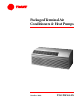
PackagedTerminal Air Conditioners & Heat Pumps October 2000 PTAC-PRC001-EN
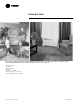
Introduction The new Trane packaged terminal air conditioners (PTACs) and heat pumps are ideally suited for offices, apartments, hotels, motels and institutional homes. Key benefits which make the units a wise choice are: • Energy efficiency • Reliability • Quiet operation • Comfort • Easy-to-use controls • Attractive and compact design • Ease of installation and servicing ©American Standard Inc.
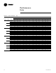
Contents Introduction Features and Benefits 2 Application Considerations 6 Selection Procedure 7 4 Model Number Description 7 8 Performance Data Cool and Heat Performance 8 15 Electric Power Power Connection Wiring Dimension and Weights 15 16 Mechanical Specifications 20 Options Warranty PTAC-PRC001-EN 22 24 3
Features and Benefits Energy Efficiency Trane PTAC units and heat pumps are among the most efficient in the industry, with EERs of up to 11.6 and COPs of up to 3.3. The efficient design of the PSC motor and airflow pattern help to reduce the energy consumption of the fan. Packaged terminal heat pumps tend to be more efficient than electric heat only. In fact, operating savings may result in a payback of less than one year.
Features and Benefits Remote Thermostat Control Each unit is built to be operated from a remote-mounted thermostat, if desired. Even if it is started without a remote, a built-in low voltage power source can accommodate a large variety of thermostat choices — manual, auto changeover or programmable — at a later date.
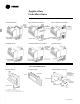
Application Considerations Curtain Wall Installation Block and Brick Veneer Installation Frame and Brick Veneer Installation Panel Wall Installation Panel Wall and Block Veneer Installation Optional Leveling Leg On applications not requiring subbase or leveling legs, unit may be flush mounted to floor. Sleeve Installation Data Framing for Wall Case Framing With Lintel Attaching Wall Sleeve to Opening 1. 3¼” minimum with subbase. 2.
Model Number Description MODEL NOMENCLATURE PT E C 090 1 G * A Digits 1,2 — Packaged Terminal Air Conditioner Digit 3 — Product Type E = Air Conditioner H = Heat Pump Digit 4 — Development Sequence C =Third Development Digits 5,6,7 — Unit Cooling Capacity 070 = 7,000 Btu 090 = 9,000 Btu 120 = 12,000 Btu 150 = 15,000 Btu Digit 8 — Main Power Supply 1 = 208-230/60/1 2 = 265/60/1 Digit 9 — Electric Heating Capacity** 0 = No Electric Heat – Air Conditioners Only E = 2.5 kW G = 3.5 kW (208-230V) G = 3.
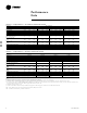
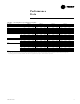
Performance Data Table PD-1 — Cooling Performance — Air Conditioner with Electric Heat Models Model Type Model No.1 & 5 Voltage3 Capacity (Btu)6 Amps Watts EER Unit without Electric Heater Min. Circuit/Ampacity 2 & 4 cfm (cool, wet coil) High Low cfm (dry coil) High Low Ventilated Air, cfm (fan only) Dehumidification (pints/hr.) Net wt. (approximate lbs.) Shipping wt. (approximate lbs.) Air Conditioner 208 7000 3.0 600 11.6 PTEC 07 230 7100 2.8 610 11.6 208 8900 3.8 785 11.3 PTEC 09 230 9100 3.
Performance Data Table PD-3 — Heat Pump Reverse Cycle Heating Capacity (Btu) Model No.1 Voltage3 Amps Watts Btu2 COP2 cfm (dry) Heating2 Btu °F Outdoor Ambient Rating Point 2 Watts Outdoor Ambient 62 57 52 47 (COP) 42 37 32 62 57 52 47 42 37 32 208 3.0 550 6200 3.3 230 PTHC 07 230 2.6 570 6400 3.3 235 265 2.2 570 6400 3.3 235 208 3.6 730 8000 3.2 230 PTHC 09 230 3.2 740 8100 3.2 235 265 2.6 740 8100 3.2 235 208 5.1 1000 10600 3.1 290 PTHC 12 230 4.5 1020 10800 3.1 310 265 3.9 1020 10800 3.
Performance Data Table PD-4 — PTEC Air Conditioner — 208V Nominal Unit Size WBT Ent Indoor Coil (°F) 61 07 67 73 61 09 67 73 61 12 67 73 61 15 67 73 DBT Ent Indoor Coil (°F) 75 80 85 75 80 85 75 80 85 75 80 85 75 80 85 75 80 85 75 80 85 75 80 85 75 80 85 75 80 85 75 80 85 75 80 85 Outdoor Temperature (°F) Total Btu 6680 6930 7205 7440 7345 7390 8335 8245 8150 8385 8335 8480 9510 9410 9255 10710 10585 10450 11265 11220 11505 12770 12630 12425 14435 14260 14070 13245 13140 13465 15035 14845
Performance Data Table PD-5 — PTEC Air Conditioner — 230/265V Nominal Unit Size 07 09 12 15 WBT Ent DBT Ent Indoor Indoor Coil Coil (°F) (°F) 75 61 80 85 75 67 80 85 75 73 80 85 75 61 80 85 75 67 80 85 75 73 80 85 75 61 80 85 75 67 80 85 75 73 80 85 75 61 80 85 75 67 80 85 75 73 80 85 Outdoor Temperature (°F) Total Btu 6780 7030 7305 7540 7445 7490 8435 8345 8250 8585 8535 8680 9710 9610 9455 10910 10785 10650 11365 11320 11605 12870 12730 12525 14535 14360 14170 13445 13340 13665 15235 15045 14775 1
Performance Data Table PD-6 — PTHC Heat Pump — 208V Nominal Unit Size 07 09 12 15 WBT Ent DBT Ent Indoor Indoor Coil Coil (°F) (°F) 75 61 80 85 75 67 80 85 75 73 80 85 75 61 80 85 75 67 80 85 75 73 80 85 75 61 80 85 75 67 80 85 75 73 80 85 75 61 80 85 75 67 80 85 75 73 80 85 Outdoor Temperature (°F) Total Btu 6680 6930 7205 7440 7345 7390 8335 8245 8150 8290 8225 8285 9420 9305 9145 10610 10480 10345 11165 11120 11405 12670 12530 12325 14335 14160 13970 13055 12955 13275 14820 14635 14370 16635 16540
Performance Data Table PD-7 — PTHC Heat Pump — 230/265V Nominal Unit Size 07 09 12 15 WBT Ent DBT Ent Indoor Indoor Coil Coil (°F) (°F) 75 61 80 85 75 67 80 85 75 73 80 85 75 61 80 85 75 67 80 85 75 73 80 85 75 61 80 85 75 67 80 85 75 73 80 85 75 61 80 85 75 67 80 85 75 73 80 85 Outdoor Temperature (°F) Total Btu 6780 7030 7305 7540 7445 7490 8435 8345 8250 8490 8425 8485 9620 9505 9345 10810 10680 10545 11365 11320 11605 12870 12730 12525 14535 14360 14170 13255 13155 13475 15020 14835 14570 16835 1
Performance Data Table PD-8 — Heating Capacity — Water gpm 1.00 1.13 1.25 1.38 1.50 1.63 1.75 1.88 2.00 2.13 2.25 2.38 2.50 2.63 2.75 Pressure Drop (psig) 2-Way Coil Valve 0.93 0.19 1.03 0.24 1.14 0.30 1.26 0.36 1.40 0.43 1.55 0.50 1.71 0.58 1.89 0.66 2.10 0.76 2.32 0.85 2.57 0.96 2.84 1.07 3.14 1.18 3.48 1.30 3.85 1.
Electric Power Table EP-1 — Electric Heat Capacity and Electrical Data (For PTEC and PTHC Models)*** Electric Voltage 2 208/230 208/230 208/230 265 265 265 Heater Size (kW) 2.0/2.5 2.9/3.5 4.1/5.0 2.5 3.7 5.0 Nominal Heating No. Of Stages 1 1 ** 1 1 ** Btu 208 6,800 9,900 14,000 — — — Btu 230 8,500 12,000 17,100 — — — Minimum Circuit Overcurrent Btu 265 — — — 8,500 12,600 17,100 Total Watts4 2,140/2,650 3,040/3,650 4,240/5,150 2,650 3,850 5,150 Total Amps 10.2/11.5 14.5/15.8 20.3/22.3 10 14.6 19.
Dimension and Weights Unit with Wall Sleeve and Subbase Accessory Top View Front View Right Side View Notes: 1. Allow a minimum of 31/4” clearance between cabinet and floor to permit installation of options subbase. 2. Allow minimum of 3” clearance between cabinet and side walls to permit front panel removal. 3. Drain tube can be mounted either right side, left side or bottom of sleeve. Bottom drain to be located by customer. Drain kit shipped separate. 4. Unit provides 20 percent outside air. 5.
Dimension and Weights Field Supplied Extension PTAC-PRC001-EN 17
Dimension and Weights Hydronic Heat Kit NOTE: Wall sleeve must extend exactly 3 inches from finished interior wall Notes: 1. This kit completely encloses all plumbing and coils, but still allows easy access to controls. 2. The chassis can slide out for easy service without removing hydronic plumbing. 3. The kits feature left or right-hand piping. 4. Unit retains complete service access with kit installed.
Dimension and Weights Duct Package When two adjacent rooms need to be conditioned, a main duct kit and a duct extension kit are possible options.These kits transfer air from one room to another, yet allow different air flows for the rooms (airflow distribution can be adjusted from 65/45 to 80/20.) Front View Duct Termination Kit The Duct Termination Kit includes a grille and a sleeve for fitting duct or duct extension through the wall.
Mechanical Specifications Unit Chassis Condenser/Evaporator Fans Outside Air Damper/Vent Control Each unit will be slide-out design shipped with room cabinet front installed. Unit chassis will have the ability to be installed with zero reversing clearance from finished floor. An electrical power cord will be included with chassis and installed by the manufacturer to assure proper NEMA 6 or 7 configuration and UL approved length.
Mechanical Specifications Unit Controls Load Shedding Terminals The unit controls will be full solid-state and accessible from the top.The standard unit mounted controls will include two rotary (switch) knobs controlling unit operational and temperature mode.The unit operational switch includes: • Off position. • Fan only — unit operates on low fan speed. • Low cool — unit operates on low fan speed to circulate air for cooling. • High cool — unit operates on high fan speed to circulate air for cooling.
Options Options Power Disconnect Switch Kit Control Valves Wall Sleeves Wall sleeves shall be industry standard size of 13¾”D x 42”W x 161/16”H. A power disconnect switch must be installed in hard-wire junction or subbase for use as a physical disconnect where required by local codes. Extended Wall Sleeves Circuit Breaker Kit 24 volt water valves are available in either two-way or three-way for 208/230 volt units and 265 volt units.
Options Subbase Kit Condensate Drain Kit Deflector Baffle Kit The fully skirted subbase conceals wiring while providing strong support. A plug-in receptacle and field wiring access expedites installation. Electrical accessories such as fuse holders, circuit breakers and disconnect switches meet N.E.C. requirements. This kit attaches to the wall sleeve base pan for controlled internal or external disposal of condensate and defrost water. The kit includes two air deflection baffles.
Warranty Warranty Information Standard Warranty •Full First-Year Warranty Trane will repair or replace, free of charge including labor, any part which proves to be defective due to workmanship or materials. •Full Five-Year Sealed System Warranty Trane will repair or replace, free of charge including labor, the evaporator, condenser, compressor or connecting tubing which proves to be defective due to workmanship or materials.
The Trane Company An American Standard Company www.trane.com Literature Order Number PTAC-PRC001-EN File Number PL-UN-PTAC-PRC001-EN-10-00 Supersedes PTAC-DS-1 6/98 Stocking Location Inland - La Crosse For more information contact your local distributor (dealer), local district office, or Since TheTrane Company has a policy of continuous product and product data improvement, it reserves the e-mail us at comfort@trane.com right to change design and specifications without notice.