Application Guide Tube Size and Component Selection RAUJ Split Systems (20-120 Tons) R-410A Refrigerant Fin and Tube Condensers SAFETY WARNING Only qualified personnel should install and service the equipment. The installation, starting up, and servicing of heating, ventilating, and air-conditioning equipment can be hazardous and requires specific knowledge and training. Improperly installed, adjusted or altered equipment by an unqualified person could result in death or serious injury.
Warnings, Cautions and Notices Warnings, Cautions and Notices. Note that warnings, cautions and notices appear at appropriate intervals throughout this manual. Warnings are provided to alert installing contractors to potential hazards that could result in death or personal injury. Cautions are designed to alert personnel to hazardous situations that could result in personal injury, while notices indicate a situation that could result in equipment or property-damage-only accidents.
Warnings, Cautions and Notices WARNING Personal Protective Equipment (PPE) Required! Installing/servicing this unit could result in exposure to electrical, mechanical and chemical hazards. • Before installing/servicing this unit, technicians MUST put on all Personal Protective Equipment (PPE) recommended for the work being undertaken. ALWAYS refer to appropriate MSDS sheets and OSHA guidelines for proper PPE.
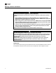
Table of Contents Overview . . . . . . . . . . . . . . . . . . . . . . . . . . . . . . . . . . . . . . . . . . . . . . . . . . . . . . . . . . . . . . 1 Background . . . . . . . . . . . . . . . . . . . . . . . . . . . . . . . . . . . . . . . . . . . . . . . . . . . . . . . 1 Updated Guidelines . . . . . . . . . . . . . . . . . . . . . . . . . . . . . . . . . . . . . . . . . . . . . . . . 2 Liquid Lines . . . . . . . . . . . . . . . . . . . . . . . . . . . . . . . . . . . . . . . . . . . . . . . . . .
iv SS-APG007-EN
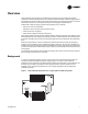
Overview Trane’s RAUJ 20- through 120-ton condensing unit product line incorporating fin and tube condenser coils has been designed for use only with R-410A and POE oil. R-410A is a high-pressure refrigerant that requires the other components of the system, including the evaporator, to be rated for R-410A pressures. For compressor lubrication, the refrigerant requires POE oil. Traditionally, refrigerant piping practices were guided by four principles: • Return the oil to the compressor.
Overview The origin of the requirements for equivalent line lengths of components, line pressure drop, and minimum and maximum refrigerant velocities is uncertain. It appears likely that at least some of the supporting data was derived from measurements and/or equations involving water. Some resource materials even show water components when illustrating refrigerant piping requirements.
Overview Equipment Placement Minimize Distance Between Components For a split air-conditioning system to perform as reliably and inexpensively as possible, the refrigerant charge must be kept to a minimum. To help accomplish this design goal: • Site the outdoor unit as close to the indoor unit as possible. • Route each interconnecting refrigerant line by the shortest and most direct path so that line lengths and riser heights are no longer than absolutely necessary.
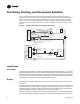
Line Sizing, Routing, and Component Selection Figure 4 illustrates an example of an RAUJ split-system component arrangement. Use it to determine the proper, relative sequence of the components in the refrigerant lines that connect the RAUJ condensing unit to an evaporator coil. Refer to “Examples of Field-Installed Evaporator Piping,” p. 13, for more detailed schematics of evaporator piping.
Line Sizing, Routing, and Component Selection valve discharges to the condenser to prevent excessive pressures from developing in the liquid line during the off cycle, due to a temperature change of the trapped column of liquid between the solenoid valve and check valve. Insulation The liquid line is generally warmer than the surrounding air, so it does not require insulation. In fact, heat loss from the liquid line improves system capacity because it provides additional subcooling.
Line Sizing, Routing, and Component Selection For improved modulation, choose expansion valves with balanced port construction and external equalization. Table 3, p. 19, identifies the part number of the valve suggested for commercial RAUJ systems. The tonnage of the valve should represent the tonnage of the portion of coil that the TXV/distributor will feed. Ball Shutoff Valves Adding manual, ball-type shutoff valves upstream and downstream of the filter simplifies replacement of the filter core.
Line Sizing, Routing, and Component Selection Components Installing the suction line requires field installation of these components: a filter, access port, Frostat™ control for coil frost protection, and ball shutoff valve. Position them as close to the compressor as possible. Table 2, p. 18, identifies suitable components by part number for each RAUJ model. Note: Placement of the Frostat control is illustrated in Figure 4, p. 4.
Expansion Valves Expansion valves meter refrigerant into the evaporator under controlled conditions. If there is too much refrigerant, the refrigerant will not completely vaporize and the remaining liquid will slug the compressor. If there is too little refrigerant, there may not be enough cooling for the compressor. Table 3, p. 19, lists expansion valves. Each evaporator distributor requires a dedicated expansion valve in order to maintain proper coil distribution.
Controls The RAUJ unit is available with different control options depending on unit tonnage. These control options include VAV operation, CV operation, chilled-water operation and a “no controls” option. The no controls option is often selected when a controls contractor wants to stage the RAUJ compressors. It is important to understand that when the staging of compressors is turned over to a third party, the compressor protection, provided through system stability, is also turned over to the third party.
Hot Gas Bypass Many years ago, hot gas bypass (HGBP) was successfully added to HVAC systems to correct a number of operational problems. Hoping to avoid such problems altogether, it eventually became common practice for designers to specify hot gas bypass in new systems. Unfortunately, the practice often degraded rather than improved reliability. Hot gas bypass increases the minimum refrigerant charge; it also inflates the first cost of the system.
Remodel, Retrofit, or Replacement Inevitably, older condensing units and evaporator systems will need to be replaced or retrofitted. Due to the phase-out of many of these older refrigerants, the major components for those older units or systems may no longer be available. The only option will be to convert the system to R-410A, POE oil, and R-410A components.
Remodel, Retrofit, or Replacement NOTICE: Compressor Damage! POE oil is hygroscopic – it absorbs water directly from the air. This water is nearly impossible to remove from the compressor oil and can cause compressor failures. For this reason, the system should not be open for longer than necessary, dry nitrogen should flow in the system while brazing, and only new containers of oil should be used for service and maintenance. All Codes take precedence over anything written here.
Examples of Field-Installed Evaporator Piping Single-Circuit RAUJs Figure 5. Type UF evaporator coil with one distributor 1. Pitch the liquid line slightly — 1 in. / 10 ft (1 cm / 3 m) — so that the refrigerant drains toward the evaporator. 2. Provide one expansion valve per distributor. 3. Slightly pitch the outlet line from the suction header toward the suction riser — that is, 1 in. / 10 ft (1 cm / 3 m) in the direction of flow. Use the tube diameter that matches the suction-header connection. 4.
Examples of Field-Installed Evaporator Piping Figure 7. 1. Type UF evaporator coil with four distributors Pitch the liquid line slightly — 1 in. / 10 ft (1 cm / 3 m) — so that the refrigerant drains toward the evaporator. 2. Provide one expansion valve per distributor. 3. Slightly pitch the outlet line from the suction header toward the suction riser — that is, 1 in. / 10 ft (1 cm / 3 m) in the direction of flow. Use the tube diameter that matches the suction-header connection. 4.
Examples of Field-Installed Evaporator Piping Dual-Circuit RAUJs Figure 8. Type UF evaporator coil with two distributors 1. Pitch the liquid lines slightly — 1 in. / 10 ft (1 cm / 3 m) — so that the refrigerant drains toward the evaporator. 2. Provide one expansion valve per distributor. 3. Slightly pitch the outlet line from the suction header toward the suction riser — that is, 1 in. / 10 ft (1 cm / 3 m) in the direction of flow. Use the tube diameter that matches the suction-header connection. 4.
Examples of Field-Installed Evaporator Piping Figure 9. Type UF evaporator coil with four distributors 1. Pitch the liquid line slightly — 1 in. / 10 ft (1 cm / 3 m) — so that the refrigerant drains toward the evaporator. 2. Provide one expansion valve per distributor. 3. Slightly pitch the outlet line from the suction header toward the suction riser — that is, 1 in. / 10 ft (1 cm / 3 m) in the direction of flow. Use the tube diameter that matches the suction-header connection. 4.
Examples of Field-Installed Evaporator Piping Figure 10. Type UF evaporator coil with eight distributors 2 Provide one expansion valve per distributor. 3 Slightly pitch the outlet line from the suction header toward the suction riser — that is, 1 in. / 10 ft (1 cm / 3 m) in the direction of flow. Use the tube diameter that matches the suction-header connection. 5 Use the “horizontal” tube diameter identified in Table 2, p. 18.
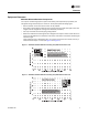
Parts Table 2. Component selection summary UNIT Refrigerant ckts Minimum step (tons) RAUJC20 RAUJC25 RAUJC30 RAUJC40 RAUJC50 RAUJC60 1 1 1 2 2 2 2 2 2 10 10 15 10 11.7 15 15 15 20 SUCTION LINE RAUJC80 RAUJD100 RAUJD120 SUCTION LINE Tube diameter (in.
Parts Table 3.
Trane optimizes the performance of homes and buildings around the world. A business of Ingersoll Rand, the leader in creating and sustaining safe, comfortable and energy efficient environments, Trane offers a broad portfolio of advanced controls and HVAC systems, comprehensive building services, and parts. For more information, visit www.Trane.com. Trane has a policy of continuous product and product data improvement and reserves the right to change design and specifications without notice.