
Programming Guide


30 VAV-SVP01A-EN
VAV Start Up/Check Out Procedure
Setting the Receiver Address
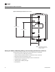
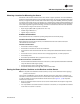
1. Using a small screwdriver, set the three rotary address switches (locations S1, S2, S3) on the
receiver (Figure 11, p. 30) to an address between 001 and 999.
Note: Do not use 000 as an address for installation. If you set the receiver address to 000, it will:
– Return the receiver outputs to their factory defaults indefinitely (zone temperature and
setpoint outputs: 72.5°F [22.5°C]).
– Remove all association knowledge.
– Make the receiver unable to associate with a sensor.
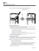
• Read the switches from left to right in the order in which they are numbered (S1, S2, S3).
• Zero is at the nine o'clock position.
2. Make a notation of the address and location of the receiver.
Setting the Sensor Address
1. Using a small screwdriver, set the three rotary address switches (locations S1, S2, S3) on the
sensor (Figure 11, p. 30) to the same address used for the receiver it is to be associated with.
2. Make a notation of the address and location where this sensor is to be mounted.
Note: Do not use 000 as an address for installation. If you set the address to 000, it will:
– Remove all association knowledge.
– Revert to a low-power hibernation mode.
– Send a disassociation request to the receiver. If the sensor and receiver are associated and
communicating at the time the sensor is set to 000 and the Test button is pressed, the
receiver will also become unassociated and will be available for re-association.
• Read the switches from left to right in the order in which they are numbered (S1, S2, S3).
• Zero is at the 9 o'clock position.
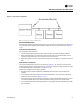
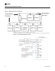
Figure 11. Setting the rotary address switches on the receiver and the sensor
S
5
GND
R77
C35
S1
S2
C33
LED4
S4
S5
S3
LED1
LED2
LED3
LED5
C34
J1
COMM -
24VAC/DC
SETPOINT
HEATING SET
SIGNAL
POWER
ADD
DRESS
FAN/SYSTEM
ZONE
COMM +
IN
ST
A
L
L
WIRELESS
GND
!
B1 +
INSTALL
WIRELESS
S4
S3
S2
S1
ADDRESS
STATUS
BATTERY
LED5
SIGNAL
LED3
L
E
D
2
LED1
Pb
Pb-FREE
STATUS
LED4
L
T
A
L
L
L
E
S
S
L
T
A
A
L
E
Do not remove the
insulation strip yet.