
Programming Guide


VAV-SVP01A-EN 91
Troubleshooting
• Disconnect the zone sensor terminal plug from the VV550 and using an Ohmmeter, measure
the resistance across the terminals 2 (common) and 3 (setpoint). Compare the resistance to
specified set point on sensor using Tab l e 19, p. 9 0. The resistance shown should correlate
within ± 2 degrees of setpoint shown on Table 19, p. 90 If not, the zone sensor needs to be
replaced.
3. Defective wiring or VV550
• With wires still connected to VAV VV550, disconnect zone sensor setpoint wires and check
voltage (DC) from wires that were connected to terminals 2 and 3 of zone sensor. You should
measure 5VDC. If you do not have 5VDC then see if the VAV VV550 is outputting 5VDC. This
can be done by disconnecting the wires on the VAV VV50 on terminals TB3-2 and TB3-3 and
measure the VDC. It should be 5VDC. If you have 5VDC at the VV550 the wires going to the
zone have an open. If 5VDC is not present check incoming power to the VV550 board on TB1-
1 24VAC input and TB1-2. Voltage should measure 24VAC ± 10%. If you measure the proper
voltage at on TB1-1 24VAC input and TB1-2 and no voltage at TB3-2 and TB3-3 replace VV550.
4. Zone sensor setpoint is shorted out
• Check the resistance across the wires. Disconnect wires from VV550 and zone sensor making
sure the ends are not touching each other and measure resistance. It should be infinity or
no conductivity. If lower resistance is shown wires are shorted together and needs to be
replaced.
Wireless Zone Sensor Failure Procedures
In the event that the VV550 reports an incorrect zone Temperature/setpoint, properly inspect the
following:
Note: No special tools or software are necessary to service and test the wireless zone sensor
system. The system can be testing by using the following: 1) LEDs 1, 2, 3, and 5 on the sensor
and on the receiver; 2) The Test button (S5) on the sensor; 3) The address test mode on the
receiver; and 4) A common volt-ohm meter.
Diagnostics
Note: Reading diagnostics can show if the sensor has an issue or it has not been setup properly.
Use this information as a starting point
• LED1, LED2, and LED3 will respond to diagnostics by exhibiting specific blinking patterns. They
will occur on the sensor as a result of pressing the Test button (S5) (Table 23, p. 93). They will
occur on the receiver independently of any user action (Table 23, p. 93).
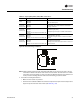
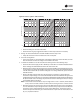
Figure 55. Wireless sensor set components with base plates removed
LED 1
LED 2
LED 3
LED 5
LED 1
LED 2
LED 3
LED 5