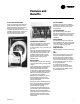
Packaged Rooftop Air Conditioners 27 ½ to 50Ton - 60 Hz Voyager™ Commercial October 2001 RT-PRC007-EN
Introduction Packaged Rooftop Air Conditioners Through the years,Trane has designed and developed the most complete line of Packaged Rooftop products available in the market today.Trane was the first to introduce the Micro —microelectronic unit controls— and again moved ahead with the introduction of the Voyager Commercial products. The Voyager Commercial line offers 27½ to 50 ton models; five sizes to meet the changing demands of the commercial rooftop market.
Contents Introduction Features and Benefits 2 4 Application Considerations 10 Selection Procedure 12 Model Number Description General Data 14 15 Performance Data 19 Performance Adjustment Factors RT-PRC007-EN Controls 18 28 Electric Power 32 Dimension and Weights 34 Mechanical Specifications 41 3
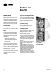
Features and Benefits Standard Features • Factory installed and commissioned microelectronic controls • Trane 3-D™ Scroll Compressors • Dedicated downflow or horizontal configuration • CV or VAV control • FROSTAT™ coil frost protection on all units • Supply air overpressurization protection on VAV units • Supply airflow proving • Emergency stop input • Compressor lead-lag • Occupied-Unoccupied switching • Timed override activation • FC supply fans • UL and CSA listing on standard options • Two inch standard
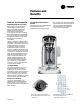
Features and Benefits Trane 3-D® Scroll Compressor Simple Design with 70% Fewer Parts Fewer parts than an equal capacity reciprocating compressor means significant reliability and efficiency benefits.The single orbiting scroll eliminates the need for pistons, connecting rods, wrist pins and valves. Fewer parts lead to increased reliability. Fewer moving parts, less rotating mass and less internal friction means greater efficiency than reciprocating compressors.
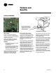
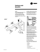
Features and Benefits Quality and Reliability Forced Combustion Blower Negative Pressure Gas Valve Hot Surface Ignitor Drum and Tube Heat Exchanger Micro Controls Drum and Tube Heat Exchanger The Micro provides unit control for heating, cooling and ventilating utilizing input from sensors that measure outdoor and indoor temperature.
Features and Benefits FC Fans with Inlet Guide Vanes Ease of Installation Trane’s forward-curved fans with inlet guide vanes pre-rotate the air in the direction of the fan wheel, decreasing static pressure and horsepower, essentially unloading the fan wheel.The unloading characteristics of aTrane FC fan with inlet guide vanes result in superior part load performance. Contractors look for lower installation (jobsite) costs. Voyager’s conversionless units provide many time and money saving features.
Features and Benefits Easy to Service Easy Access Low Voltage Terminal Board Because today’s owners are very costconscious when it comes to service and maintenance, theTrane Voyager was designed with direct input from service contractors.This valuable information helped to design a product that would get the serviceman off the job quicker and save the owner money. Voyager does this by offering: Voyager’s Low VoltageTerminal Board is external to the electrical control cabinet.
Features and Benefits VariTrac Downflow and Horizontal Economizers Trane’s changeover VAV System for light commercial applications is also available. Coupled with Voyager Commercial, it provides the latest in technological advances for comfort management systems and can allow thermostat control in every zone served by VariTrac™. The economizers come with three control options dry bulb, enthalpy and differential enthalpy.
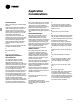
Application Considerations Exhaust Air Options amounts of outdoor air into the building. If, however, building pressure is not of a critical nature, the non-modulating exhaust fan may be sized for more than 50 percent of design supply airflow. ConsultTable PD-16 for specific exhaust fan capabilities with Voyager Commercial units. 3 Barometric Relief Dampers 5 Bhp must be multiplied by the air density ratio to obtain the actual operating bhp.
Application Considerations Heat selections other than gas heat will not be affected by altitude. Nominal gas capacity (output) should be multiplied by the factors given inTable PD-3 before calculating the heating supply air temperature. Acoustical Considerations Proper placement of rooftops is critical to reducing transmitted sound levels to the building.The ideal time to make provisions to reduce sound transmissions is during the design phase.
Selection Procedure Selection ofTrane commercial air conditioners is divided into five basic areas: 1 Cooling capacity 2 Heating capacity 3 Air delivery 4 Unit electrical requirements 5 Unit designation b 2” Hi-efficiency throwaway filters. c Step 4 — Determine total required unit cooling capacity: Exhaust fan. d Required capacity = total peak load + O.A. load + supply air fan motor heat. Economizer cycle. Step 1 — A summation of the peak cooling load and the outside air ventilation load shows: 27.
Selection Procedure Heating capacity selection: 1 Winter outdoor design conditions—5 F. 2 Total return air temperature — 72 F. 3 Winter outside air minimum ventilation load and cfm — 1,200 cfm and 87.2 MBh. 4 Peak heating load 225 MBh. Utilizing unit selection in the cooling capacity procedure. Mixed air temperature = RADB + %O.A. (OADB - RADB) = 72 + (0.10) (0-72) = 64.8 F. Supply air fan motor heat temperature rise = 20,600 BTU ÷ (1.085 x 12,000) cfm = 1.6 F.
Model Number Description YC 12 D 3 480 456 A 7 4 8 H 9 A 1 10 11 A 4 12 13 F 14 D 1 A 15 16 17 0 0 0 0 0 0 0 18 19 20 21 22 23 24 0 0 25 26 0 0 05 27 28 29 Digit 1, 2 — Unit Function Digit 13 — Supply Fan Motor, HP Digit 16 — System Control TC = DX Cooling, No Heat TE = DX Cooling, Electric Heat YC = DX Cooling, Natural Gas Heat 1 = 7.5 Hp Std. Eff. 2 = 10 Hp Std. Eff. 3 = 15 Hp Std. Eff. 4 = 20 Hp Std. Eff. 5 = 7.5 Hp Hi. Eff. 6 = 10 Hp Hi. Eff. 7 = 15 Hp Hi. Eff. 8 = 20 Hp Hi. Eff.
General Data Table GD-1 — General Data — 27 1/2 - 30 Tons 27 1/2 Ton Cooling Performance1 Nominal Gross Capacity Natural Gas Heat2 Heating Input (BTUH) First Stage Heating Output (BTUH) First Stage Steady State Efficiency (%)3 No. Burners No. Stages Gas Connection Pipe Size (in.) Electric Heat KW Range5 Capacity Steps: Compressor Number/Type Size (Nominal) Unit Capacity Steps (%) Motor RPM Outdoor Coil — Type Tube Size (in.) OD Face Area (sq. ft.) Rows/Fins Per Inch Indoor Coil — Type Tube Size (in.
General Data Table GD-2— General Data — 35-40 Ton 35 Ton Cooling Performance1 Nominal Gross Capacity Natural Gas Heat2 Heating Input (BTUH) First Stage Heating Output (BTUH) First Stage Steady State Efficiency (%)3 No. Burners No. Stages Gas Connection Pipe Size (in.) Electric Heat KW Range5 Capacity Steps: Compressor Number/Type Size (nominal) Unit Capacity Steps (%) Motor RPM Outdoor Coil — Type Tube Size (in.) OD Face Area Rows/Fins Per Inch Indoor Coil — Type Tube Size (in.) OD Face Area (sq. ft.
General Data Table GD-3— General Data — 50 Ton Table GD-4 — Economizer Outdoor Air Damper Leakage (Of Rated Airflow) 50 Ton Cooling Performance1 Nominal Gross Capacity Natural Gas Heat2 Heating Input (BTUH) First Stage Heating Output (BTUH) First Stage Steady State Efficiency (%)3 No. Burners No. Stages Gas Connection Pipe Size (in.) Electric Heat KW Range5 Capacity Steps: Compressor Number/Type Size (nominal) Unit Capacity Steps (%) Motor RPM Outdoor Coil — Type Tube Size (in.) OD Face Area (sq. ft.
Performance Adjustment Factors Table PD-1— Enthalpy of Saturated AIR Wet Bulb Temperature 40 41 Figure PD-1 — Air Density Ratios Altitude/Temperature Correction Btu Per Lb. 15.23 15.70 42 16.17 43 16.66 44 45 17.15 17.65 46 18.16 47 18.68 48 19.21 49 50 19.75 20.30 51 20.86 52 21.44 53 22.02 54 55 22.62 23.22 56 23.84 57 24.48 58 25.12 59 60 25.78 26.46 61 27.15 62 27.85 63 28.57 64 65 29.31 30.06 66 30.83 67 31.62 68 32.42 69 70 33.25 34.09 71 34.
Performance Data Table PD-4 — 27 1/2 Ton Gross Cooling Capacities (MBh) Ent DB 61 67 73 (F) TGC SHC TGC SHC TGC SHC Ambient Temperature — Deg F 95 105 Entering Wet BulbTemperature — Deg F 61 67 73 61 67 73 TGC SHC TGC SHC TGC SHC TGC SHC TGC SHC TGC SHC 61 67 73 TGC SHC TGC SHC TGC SHC 75 80 85 90 291 294 301 317 228 268 301 317 323 324 325 328 185 220 258 297 358 359 360 361 130 171 210 248 278 281 290 306 221 309 174 343 123 261 310 212 343 164 290 311 251 344 203 306 315 290 345 241 265 268
Performance Data Table PD-6 — 35 Ton Gross Cooling Capacities (Mbh) 85 CFM Ent DB 61 67 73 (F) TGC SHC TGC SHC TGC SHC AmbientTemperature — Deg F 95 105 Entering Wet Bulb Temperature — Deg F 61 67 73 61 67 73 TGC SHC TGC SHC TGC SHC TGC SHC TGC SHC TGC SHC 61 67 73 TGC SHC TGC SHC TGC SHC 115 75 10500 80 85 90 377 383 398 419 310 367 398 419 416 417 420 426 240 296 351 409 459 460 461 462 166 224 281 336 361 366 383 404 301 359 383 404 398 399 402 408 231 287 343 400 438 439 440 442 158 2
Performance Data Table PD-8 — 50 Ton Gross Cooling Capacities (MBh) 85 Ent DB CFM (F) 61 67 73 61 Ambient Temperature — Deg F 95 105 Entering Wet Bulb Temperature — Deg F 67 73 61 67 115 73 61 67 73 TGC SHC TGC SHC TGC SHC TGC SHC TGC SHC TGC SHC TGC SHC TGC SHC TGC SHC TGC SHC TGC SHC TGC SHC 75 15000 80 85 90 556 565 590 623 459 547 590 623 614 356 679 244 616 439 680 331 622 524 682 417 631 611 684 500 529 539 567 599 444 533 567 599 585 588 593 604 342 424 509 597 647 649 651 654
Performance Data Table PD-9 — Electric Heat Air Temperature Rise KW Input 36 54 72 90 108 Total MBH 123 184 246 307 369 8000 14.2 21.2 28.3 35.4 — 9000 12.6 18.9 25.2 31.5 — 10000 11.3 17.0 22.6 28.3 — 11000 10.3 15.4 20.6 25.7 — 12000 9.4 14.2 18.9 23.6 28.3 Cfm 14000 8.1 12.1 16.2 20.2 24.3 13000 8.7 13.1 17.4 21.8 26.1 15000 7.6 11.3 15.1 18.9 22.6 16000 — 10.6 14.2 17.7 21.2 17000 — 10.0 13.3 16.7 20.0 18000 — 9.4 12.6 15.7 18.9 19000 — 8.9 11.9 14.9 17.9 20000 — 8.5 11.3 14.2 17.
Performance Data Table PD-12 — Supply Fan Performance — 27½ - 35 Ton SCFM 8000 8500 9000 9500 10000 10500 11000 11500 12000 12500 13000 13500 14000 14500 0.25 RPM BHP 341 1.39 355 1.60 368 1.84 382 2.10 396 2.39 410 2.71 425 3.07 440 3.46 455 3.89 470 4.34 485 4.84 501 5.36 516 5.91 532 6.51 0.50 RPM BHP 401 1.85 412 2.08 423 2.35 435 2.64 448 2.96 461 3.31 474 3.68 488 4.08 501 4.52 515 4.98 528 5.47 542 6.00 555 6.58 570 7.20 0.75 RPM BHP 451 2.30 462 2.58 473 2.88 484 3.20 495 3.53 506 3.89 518 4.
Performance Data Table PD-13 — Supply Fan Performance — 40 and 50 Ton 0.25 SCFM 0.50 0.75 1.00 Static Pressure (in. wg)1 1.25 1.50 1.75 2.00 2.25 2.50 RPM BHP RPM BHP RPM BHP RPM BHP RPM BHP RPM BHP RPM BHP RPM BHP RPM BHP RPM BHP 12000 13000 365 388 3.02 3.73 408 427 3.66 4.40 448 468 4.32 5.13 485 501 4.99 5.84 522 536 5.70 6.57 556 569 6.44 7.34 588 601 7.20 8.15 620 631 7.96 8.96 652 660 8.75 9.80 682 690 9.56 10.
Performance Data Table PD-14 — Component Static Pressure Drops (in. W.G.)1 Heating System Nominal Tons CFM Std Air 8000 27½ 30 35 40 50 Gas Heat Electric Heat3 1 Element 2 Element 0.05 0.06 ID Coil Adder 0.00 Filters2 High Eff. Filters 2” 4” 0.04 0.03 Inlet Guide Vanes 0.05 Low 0.08 High 0.06 Economizer 0.04 9000 0.10 0.08 0.07 0.07 0.00 0.05 0.04 0.07 0.04 10000 0.13 0.10 0.08 0.09 0.00 0.06 0.05 0.08 0.05 11000 0.15 0.12 0.10 0.11 0.00 0.08 0.05 0.10 0.
Performance Data Table PD-15 — Supply Air Fan Drive Selections 7.
Performance Data Table PD-16— Power Exhaust Fan Performance Exhaust Airflow (Cfm) External Static Pressure — Inches of Water High Speed Med Speed Low Speed ESP ESP ESP 3500 0.900 — — 4000 0.860 — — 4500 0.820 — — 5000 0.780 — 0.400 0.380 5500 0.745 — 6000 0.700 — 0.360 6500 0.660 — 0.330 7000 0.610 0.400 0.300 7500 0.560 0.365 0.260 8000 0.505 0.330 0.215 8500 0.445 0.300 0.170 9000 0.385 0.255 0.120 9500 0.320 0.210 0.070 10000 0.255 0.165 0.
Controls VAV Units Only Variable Frequency Drives (VFD) Control Sequence of Operation Variable frequency drives are driven by a modulating 0-10 vdc signal from the VAV module. A pressure transducer measures duct static pressure, and the VFD is modulated to maintain the supply air static pressure within an adjustable user-defined range. The range is determined by the supply air pressure setpoint and supply air pressure deadband, which are set through a unit mounted potentiometer.
Controls reset temperature setpoint the amount of reset is equal to the reset amount setpoint. Morning Warm-up setpoint is set at the unit mounted VAV Setpoint panel or at a remote panel. b Morning Warm-up (MWU) Reset Based On Zone Or Return Temperature Morning warm-up control (MWU) is activated whenever the unit switches from unoccupied to occupied and the zone temperature is at least 1.5 F below the MWU setpoint.
Controls the requirement, the UCP will energize the second stage electric heat contactor(s) if the appropriate limits are closed.The UCP will cycle second stage on and off as required while keeping stage one energized. The supply fan is energized approximately 1 second before the electric heat contactors. When the space temperature rises above the heating setpoint, the UCP deenergizes the supply fan and all electric heat contactors.
Controls Coil Freeze Protection FROSTAT™ The FROSTAT system eliminates the need for hot gas bypass and adds a suction line surface temperature sensor to determine if the coil is in a condition of impending frost. If impending frost is detected primary cooling capacity is shed as necessary to prevent icing. All compressors are turned off after they have met their minimum 3 minute on times.
Electrical Data Electrical Service Sizing DSS = 1.15 x (LOAD1 + LOAD2 + LOAD4) To correctly size electrical service wiring for your unit, find the appropriate calculations listed below. Each type of unit has its own set of calculations for MCA (Minimum Circuit Ampacity), MOP (Maximum Overcurrent Protection), and RDE (Recommended Dual Element fuse size). Read the load definitions that follow and then find the appropriate set of calculations based on your unit type.
Electrical Data Table ED-2 — 27½-50 Ton Electrical Service Sizing Data1 Compressor Allowable Electrical Voltage Model Characteristics Range TC/TE/YC*330 208/60/3 187-229 TC/TE/YC*360 TC/TE/YC*420 TC/TE/YC*480 TC/TE/YC*600 No/Ton 1/10,1/15 RLA (Ea.) 41.9/62.8 LRA (Ea.) 269/409 230/60/3 207-253 41.9/62.8 247/376 460/60/3 414-506 18.1/27.3 95/142 575/60/3 517-633 14.6/21.8 76/114 208/60/3 187-229 62.8 409 230/60/3 207-253 62.8 376 460/60/3 414-506 27.
Dimensional Data Figure DD-1 — 27 1/2 - 35 Tons (TC, TE,YC Low Heat) NOTES: 1. ALL DIMENSIONS INCHES. 2. THRU-BASE ELECTRICAL LOCATIONS ARE PRESENT ONLY WHEN OPTION IS ORDERED. 1/16 NOTE: The Two Horizontal Power Exhaust Hoods and the three Horizontal Fresh Air Hoods are located side by side. The Fresh Air Hoods (not shown) extend only 23 15/16” from the end of the unit.
Dimensional Data Figure DD-2 — 27 1/2 - 35 Tons (YC High Heat) NOTES: 1. ALL DIMENSIONS INCHES. 2. THRU-BASE ELECTRICAL LOCATIONS ARE PRESENT ONLY WHEN OPTION IS ORDERED. 1/16 3” NOTE: The Two Horizontal Power Exhaust Hoods and the three Horizontal Fresh Air Hoods are located side by side. The Fresh Air Hoods (not shown) only extend 23 15/16” from the end of the unit.
Dimensional Data NOTES: 1. ALL DIMENSIONS INCHES. 2. THRU-BASE ELECTRICAL LOCATIONS ARE PRESENT ONLY WHEN OPTION IS ORDERED. Figure DD-3 — 40-50 Tons (TC,TE, YC Low & High Heat) 1/16 4” NOTE: The Two Horizontal Power Exhaust Hoods and the three Horizontal Fresh Air Hoods are located side by side. The Fresh Air Hoods (not shown) only extend 23 15/16” from the end of the unit.
Dimensional Data (Variable Air Volume VAV) Field Installed Sensors SINGLE SETPOINT SENSOR WITH SYSTEM FUNCTION LIGHTS (BAYSENS021*) PROGRAMMABLE NIGHT-SETBACK SENSOR (BAYSENS020*) Note: 1. Remote sensors are available for use with all zone sensors to provide remote sensing capabilities.
Dimensional Data (Constant Volume CV) Field Installed Sensors PROGRAMMABLE NIGHT-SETBACK SENSOR (BAYSENS019*) DUAL SETPOINT, MANUAL/AUTOMATIC CHANGEOVER SENSOR WITH SYSTEM FUNCTION LIGHTS (BAYSENS010*) WITHOUT LED STATUS INDICATORS (BAYSENS008*) SINGLE SETPOINT WITHOUT LED STATUS INDICATORS (BAYSENS006*) Note: 1. Remote sensors are available for use with all zone sensors to provide remote sensing capabilities.
Dimensional Data (CV and VAV) Integrated Comfort™ System Sensors ZONE TEMPERATURE SENSOR W/TIMED OVERRIDE BUTTON AND LOCAL SETPOINT ADJUSTMENT (BAYSENS014)1 ZONE TEMPERATURE SENSOR W/TIMED OVERRIDE BUTTONS (BAYSENS013*) ALSO AVAILABLE SENSOR ONLY (BAYSENS017*) REMOTE MINIMUM POSITION POTENTIOMETER CONTROL (BAYSTAT023*) TEMPERATURE SENSOR (BAYSENS016*) Note: 1. Remote sensors are available for use with all zone sensors to provide remote sensing capabilities.
Weights Table W-1 — Approximate Operating Weights — Lbs.2 Basic Unit Weights1 Unit Model YC Low Heat YC High Heat TC TE **D330 **H330 **D360 **H360 **D420 **H420 **D480 **H480 **D600 **H600 3650 3650 3730 3730 3815 3815 4765 4790 4935 4960 4012 4077 4092 4142 4177 4227 4885 4915 5055 5085 3520 3565 3600 3600 3685 3685 4540 4540 4710 4710 3553 3598 3633 3633 3718 3718 4575 4575 4745 4745 Notes: 1. Basic unit weight includes minimum HP Supply Fan motor. 2.
Mechanical Specifications General The units shall be dedicated downflow or horizontal airflow.The operating range shall be between 115 F and 0 F in cooling as standard from the factory for all units. Cooling performance shall be rated in accordance with ARI testing procedures. All units shall be factory assembled, internally wired, fully charged with HCFC-22 and 100% run tested to check cooling operation, fan and blower rotation and control sequence before leaving the factory.
Mechanical Specifications make all heating, cooling and/or ventilating decisions in response to electronic signals from sensors measuring indoor and outdoor temperatures.The control algorithm maintains accurate temperature control, minimizes drift from set point and provides better building comfort. A centralized microprocessor shall provide anti-short cycle timing and time delay between compressors to provide a higher level of machine protection.
Mechanical Specifications Accessories Roof Curb The roof curb shall be designed to mate with the unit and provide support and a water tight installation when installed properly.The roof curb design shall allow field-fabricated rectangular supply/return ductwork to be connected directly to the curb when used with downflow units. Curb design shall comply with NRCA requirements. Curb shall ship knocked down for field assembly and include wood nailer strips.
Mechanical Specifications LP Conversion Kit Field installed conversion kit shall provide orifice(s) for simplified conversion to liquefied propane gas. No change of gas valve shall be required. BAYSENS006* — Zone Sensor has one temperature setpoint lever, heat, off or cool system switch, fan auto or fan on switch. Manual changeover.These sensors are for CV units only. BAYSENS008* — Zone Sensor has two temperature setpoint levers, heat, auto, off, or cool system switch, fan auto or fan on switch.
(20-60Ton) RT-PRC007-EN 45
The Trane Company An American Standard Company www.trane.com For more information contact your local district office, or e-mail us at comfort@trane.com Literature Order Number RT-PRC007-EN File Number PL-RT-TC/TE/YC-27½ - 50-TONS-PRC0007-EN-10-2001 Supersedes RT-PRC007-EN 02/01 Stocking Location Inland-LaCrosse Since The Trane Company has a policy of continuous product and product data improvement, it reserves the right to change design and specifications without notice.