
User's Manual


54
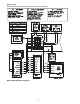
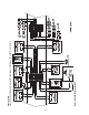
Figure 3-18
Typical GBAS Analog Input Wiring Diagram for 20 through 130 Ton CV & VAV Control Options
GBAS Voltage vs Setpoint
Unit Type
VAV CV SETPOINT Input Voltage* Setpt Range
x x Unoccupied Zone Cooling Setpoint 0.5 to 4.5 vdc 50°F to 90°F
x Occupied Zone Cooling Setpoint 0.5 to 4.5 vdc 50°F to 90°F
x x Occupied Zone Heating Setpoint 0.5 to 4.5 vdc 50°F to 90°F
x S/A Cooling Setpoint 0.5 to 4.5 vdc 40°F to 90°F
x S/A Heating Setpoint
(VAV Hydro Only) 0.5 to 4.5 vdc 40°F to 180°F
x x Space Static Pressure Setpoint 0.5 to 4.5 vdc 0.03 to 0.3 IWC
x Supply Duct Static Pressure Setpoint 0.5 to 4.5 vdc 0.00 to 5.0 IWC
Voltage Inputs less than 0.5 will be interpreted as 0.5 vdc.
Voltage Inputs higher than 4.5 will be interpreted as 4.5 vdc.
* The actual inputted value will be displayed on the Human Interface.
Refer to Wiring Notes on page 51