
User's Manual


82
Unit Start-Up (Continued)
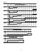
Figure 4-5
Fresh Air & Return Air Linkage Adjustment
Compressor Start-Up
(All Systems)
1. Ensure that the "System" selection switch at the remote
panel is in the "Off" position.
2. Before closing the disconnect switch, ensure that the
compressor discharge service valve and the liquid line
service valve for each circuit is back seated.
CAUTION
Compressor Damage!
Do not allow liquid refrigerant to enter the suction line.
Excessive liquid accumulation in the liquid lines may
result in compressor damage.
COMPRESSOR SERVICE VALVES MUST BE FULLY
OPENED BEFORE START-UP (SUCTION, DISCHARGE,
LIQUID LINE, AND OIL LINE).
3. Close the disconnect switch or circuit protector switch
that provides the supply power to the unit's terminal block
1TB1 or the unit mounted disconnect switch 1S14 to allow
the crankcase heater to operate a minimum of 8 hours be-
fore continuing.
Note: Compressor Damage could occur if the
crankcase heater is not allowed to operate the
minimum of 8 hours before starting the
compressor(s).
RETURN AIR
DAMPERS
FRESH AIR
DAMPERS
FILTER
SECTION
2
1
3
4
5
6
7
8
Top View
4. Turn the 115 volt control circuit switch 1S1 and the 24
volt control circuit switch 1S70 to the "On" position.
5. Open the Human Interface access door, located in the
unit control panel, and press the SERVICE MODE key to
display the first service screen. Refer to the latest edition
of the RT-SVP01A-EN for CV applications or
RT-SVP02A-EN for VAV applications for the SERVICE
TEST screens and programming instructions.
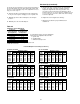
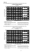
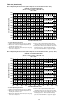
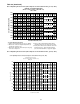
6. Use Table 4-1 to program the following system compo-
nents for operation by scrolling through the displays;
20 to 30 Ton
Compressor 1A (On)
Compressor 1B (Off)
Condenser Fans
40 through 60 Ton
Compressor 1A (On)
Compressor 1B (Off)
Compressor 2A (Off)
Compressor 2B (Off)
Condenser Fans
70 & 105 Ton
Compressor 1A & 1B (On)
Compressor 1C (Off)
Compressor 2A & 2B (Off)
Compressor 2C (Off)
Condenser Fans
115 & 130 Ton
Compressor 1A & 1B (On)
Compressor 1C & 1D (Off)
Compressor 2A & 2B (Off)
Compressor 2C & 2D (Off)
Condenser Fans
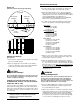
7. Attach a set of service gauges onto the suction and dis-
charge gauge ports for each circuit. Refer to Figure 4-6
for the various compressor locations.
8. Once the configuration for the components is complete,
press the NEXT key until the LCD displays the “Start test
in __Sec.” screen. Press the + key to designate the delay
before the test is to start. This service test will begin after
the TEST START key is pressed and the delay desig-
nated in this step has elapsed. Press the ENTER key to
confirm this choice.
WARNING
Rotating Components!
Disconnect all electric power, including remote discon-
nects before servicing. Follow proper lockout/tagout
procedures to ensure the power can not be inadvert-
ently energized. Failure to disconnect power before ser-
vicing could result in death or serious injury.
9. Press the TEST START key to start the test. Remember
that the delay designated in step 8 must elapse before
the system will begin to operate.
10. Once each compressor or compressor pair has started,
verify that the rotation is correct. If a scroll compressor is
rotating backwards, it will not pump and a loud rattling
sound can be observed. Check the electrical phasing at
the load side of the compressor contactor. If the phasing
is correct, before condemning the compressor, inter-