Installation Operation Maintenance RTUB 207-224 - Liquid chillers with helical rotary compressors RTCA 108-216 - Remote air-cooled condenser RLC-SVX03A-E4
Foreword These installation, operation and maintenance instructions are given as a guide to good practice in the installation, putting into service, operation, and maintenance by the user of Trane RTUB and RTCA units. They do not contain full service procedures necessary for the continued successful operation of this equipment; The services of a qualified technician should be employed through the medium of a maintenance contract with a reputable service company.
Contents Foreword 2 Warranty 2 Reception of unit 2 Cautions and warnings 2 Refrigerant 2 General information Unit Inspection 5 Inspection Checklist 5 Loose Parts Inventory 6 Description of the Unit 6 General Data RTUB 7 General Data RTCA 8 Installation RLC-SVX03A-E4 Installation Responsibilities 9 Storage 9 Special Lifting and Moving Instructions 10 Isolation 10 Foundation 10 Clearances 11 Drainage 12 Releasing the Nitrogen Holding Charge 12 Water Connections (RTUB)
Contents Operation Pre-start Checkout 21 Unit Voltage Power Supply 21 Unit Voltage Imbalance 21 Unit Voltage Phasing 21 Water System Flow Rates 22 Water System Pressure Drop 22 Daily Unit Start-up Procedure 22 Seasonal Unit Start-up Procedure 23 Temporary Shutdown and Restart 23 Extended Shutdown Procedure 23 System Restart after Extended Shutdown 23 Maintenance 4 Periodic Maintenance 25 Refrigerant and Oil Charge Management 27 R134a Field-charging Procedure 28 Charge Isolation
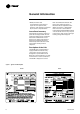
General information This manual describes installation, operation, and maintenance of RTUB and RTCA units. A separate manual is available for the use and maintenance of the RTUB controls (UCM-CLD). Unit Inspection When the unit is delivered, verify that it is the correct unit and that it is property equipped. Compare the information that appears on the unit nameplate with the ordering and submittal information. A typical unit nameplate is shown in Figure 1.
General information • Notify the Trane sales representative and arrange for repair. Do not repair the unit, however, until damage is inspected by the carrier's representative. Loose Parts Inventory Check all the accessories and loose parts that are shipped with the unit against the shipping list. Included in these items will be water vessel drain plugs, rigging and electrical diagrams, and service literature, which are placed inside the control panel and/or starter panel for shipment.
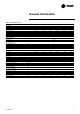
General information Table 1 - General data - RTUB Unit size Compressor Type/quantity Nominal size Evaporator Evaporator Model Water Storage Minimum Flow Maximum Flow Evaporator inlet diameter Evaporator outlet diameter Minimum Starting/ Operating Ambient Refrigerant Number of Independent Refrigerant Circuits Percent Minimum Load Refrigerant Charge Oil Charge Operating Weight Shipping Weight Unit size Compressor Type/Quantity Nominal size Evaporator Evaporator Model Water Storage Minimum Flow Maximum Flow E
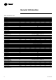
General information Table 2 - General data - RTCA Unit size Condenser Condenser type Fin spacing Frontal surface area Airflow Standard unit Low noise unit Condenser fans Number of fans Fan speed Standard unit Low noise unit Nominal fan power Standard unit Low noise unit Current fan amps Standard unit Low noise unit Minimum Starting/ Operating Ambient (1) Refrigerant Number of Independent Refrigerant Circuits Refrigerant Charge Operating Weight (2) Shipping Weight (2) Hot gas connection Liquid connection 10
Installation Installation responsibilities Generally, the contractor must do the following when installing an RTUB/RTCA unit. • Install the units on a flat foundation, level (within 1/4" [6 mm] across the length of the unit), and strong enough to support unit loading. • Install the units per the instructions contained in the Installation section of this manual. • Install any optional sensors and make electrical connections at the UCM-CLD.
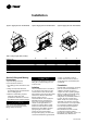
Installation Figure 2- Rigging the unit - RTUB 207-208 Figure 3- Rigging the unit - RTUB 210-224 Figure 4- Rigging the unit - RTCA 108-216 Table 3 - Sling Lengths (mm) for lifting RTUB unit size 207-208 210-211-212 214-216-217 218-220 222-224 RTCA unit size 108/109/111/208/209/211 113/115/115/213/215/216 Special Lifting and Moving Instructions A specific lifting method is recommended as follows: 1. Four lifting points are built into the unit. 2.
Installation condensation coils must be protected from side winds when their speed exceeds 16 km/h. Position the unit above the average height of snow observed in the region where it is installed. Never install temporary or permanent objects (tarp or roof) over the unit, because recycling of hot air would reduce the capacity of the condensation coils. Discharged air from the fans must not be obstructed. It is prohibited to install ducts for the fan discharge air (even short ones).
Installation Drainage Provide a large-capacity drain for water vessel drain-down during shutdown or repair. The evaporator is provided with a drain connection. All local and national codes apply. The vent on the top of the evaporator water box is provided to prevent a vacuum, by allowing air into the evaporator for complete drainage. Releasing the Nitrogen Holding Charge The nitrogen holding charge can be released into the atmosphere. C AUTION When releasing nitrogen holding charge, ventilate the room.
Installation Follow the manufacturer's instructions for the installation procedures. Flow Switch Installation 1. Mount the switch upright, with a minimum of 5 pipe diameters of straight horizontal run on each side. Do not install close to elbows, orifices, or valves. Note: The arrow on the switch must point in the direction of flow. 2. To prevent switch fluttering, remove all air from the water system. Note: The UCM-CLD waits for six seconds after a “flow loss” diagnosis before stopping the unit.
Installation Figure 8- RTUB Evaporator water pressure drops kPa Evaporator Water Pressure Drop Water Flow Rate l/s the values given by the pressure gauges, open one valve and close the other. Refrigerant Safety Valves Discharge valves are an option for the RTUB. If installation requires this valve to be mounted, it is mandatory to install two safety valves: one between the compressor and the service valve and the other after the service valve to protect the condenser.
Installation convenient position. Plug the sensor cable and the cable connected to the control panel into the junction box. The shielded cable can be cut to the required length. Note: To lengthen the sensor's power cable, use 0.75 to 1.25 mm² conductors, 600V. The cable used between the junction box and the control panel must either be shielded or in a duct. If a shielded cable is used, make sure it is not used with other cables carrying 30 V or more.
Installation Figure 10 - Detail of positions of refrigerant sensors 5R56-1 and 5R6-2 3 2 1 57 1 Sensor 2 Connector 3 Brazed connector on the condenser 16 another manufacturer's condenser in used, operation and performance may be degraded. Depending on the fan settings, malfunctioning may damage the RTUB due to instability of the high pressure.
Installation Figure 11: Units on the same level 1 2 Limitations:The distance between the two units must not exceed 60 m in reality or the equivalent of 90 m taking into account pressure drops. The height of the liquid line in relation to the unit base must be less than 5 m. It is recommended to place a trap on the discharge line at the oil separator outlet, if this discharge line is horizontal for a distance greater than 5 m, at a height greater than the connection to the oil separators.
Installation Figure 13: RTCA (or other manufacturer's condenser) below the RTUB 3 Limitations:The distance between the two units must not exceed 60 m in reality or the equivalent of 90 m taking into account pressure drops. The height of the liquid line in relation to the condenser base must be less than 5 m.
Installation Equivalent pressure drops To correctly determine the size of the liquid and discharge lines for connection on site, it is first necessary to establish the equivalent pressure drops for each line, comprising the additional flow resistances, from bends, valves, etc. As a first approximation, we can estimate the equivalent pressure drops at 1.5 times the piping length. Size of the liquid line The standpipe must not be more than 5 m above the air-cooled condenser base.
Installation Vacuum pumping For this operation, use a vane pump making it possible to obtain a partial vacuum or 100 microns or less. When pumping out to create a vacuum, it is important to connect the pump to the high and low pressure sides of the system. Follow the pump manufacturer's recommendations. The pipes used to connect the pump to the system must be made of copper, with the largest diameter possible. A large pipe diameter reduces flow resistance and shortens the duration of the vacuum pumping.
Operation Pre-start checkout Installation Checklist When installation is complete, but prior to putting the unit into service, the following pre-start procedures must be reviewed and verified: • Inspect all wiring connections to be sure they are clean and tight. WARNING Disconnect all electric power, including remote disconnects, before servicing. Failure to disconnect power before servicing can cause severe personal injury or death.
Operation motor rotation requires confirmation of the electrical phase sequence of the power supply. The motor is internally connected for clockwise rotation with the incoming power supply phased A-B-C. When rotation is clockwise, the phase sequence is usually called "ABC;" when counterclockwise, "CBA." This direction may be reversed outside the alternator by interchanging any two of the line wires.
Operation operating load. Overheating may vary slightly on the circuit if the system load is lower, when the slide valve is moving. Overheating must stabilize at approximately 4°C when the above components have stabilized. Subcooling Normal subcooling for each circuit ranges from 8-10°C, depending on the units. If subcooling for either circuit does not fall within these values, check the overheating for the circuit and adjust if necessary.
Operation System Flow Rates" and "WaterSystem Pressure Drop." 7. Adjust the flow switch on the evaporator piping for proper operation. 8. Stop the water pump. The unit is now ready for startup as described in "Startup Procedures.
Maintenance Perform all maintenance procedures and inspections at the recommended intervals. This will prolong the life of the chiller and minimize the possibility of costly failures. After the unit has been operating for approximately 30 minutes and the system has stabilized, check the operating conditions and complete the following procedures: Weekly Maintenance While the unit is running in stable conditions: 1. Check the UCM pressure for Evaporator, Condenser, and Intermediate Oil. 2.
Maintenance Figure 15 - Oil filter change 12. Charge the unit with refrigerant R134a refer to charging procedure). 1. Oil charging valve 2. Oil pressure control port 3. Oil pressure control port For units with the discharge valve option: 1. Close the angle valve placed on the refrigerant liquid line to store the refrigerant in the condenser. 2. After the compressor stops, close the compressor discharge valve and disconnect the unit. Note: Do not make successive vacuums by using the compressor.
Maintenance Some symptoms of a refrigerant under-charged unit: • Low subcooling Checking the separator oil level Figure 17 - System Oil Specifications • Larger-than-normal evaporator approach temperatures (LeavingWater Temperature - Saturated Evaporator Temperature) • Low Evaporator-Refrigerant Temperature Limit • Low Refrigerant-Temperature Cutout diagnostic 1 Oil separator 2 Valve 3 ¼" refrigeration hose 4 Sight glass 5 Minimum oil level 6 Maximum oil level • Fully-open expansion valve • Possible whis
Maintenance Some symptoms of an oil undercharged unit: • Compressor rattle or grinding sound • Lower-than-normal pressure drop through oil system [9 mm] flare). Open the service valve. 2. Add 4.5 kg of refrigerant (R134a) charge. • Seized or Welded Compressors 3. Close the valve, remove the charging hose and start the unit. Monitor subcooling. • Low oil-sump level after normal shutdown 4. If subcooling is still insufficient, return to step number 2.
Maintenance The evaporator is large enough to hold all the charge, for any unit, below the centerline of the shell. Therefore, no special precautions are required to restart the unit after isolating the charge in the evaporator. 12. Attach the vacuum hose and evacuate the liquid line. • Oil line drain (lowest point in system) 13. Remove the vacuum hose from the liquid line and attach the charging hose. • Oil cooler Filter Replacement Procedure 15. Remove the charging hose.
Maintenance Factory (initial) Oil-Charging Procedure The initial charging procedure should be followed any time the unit is new or has had all of the oil removed. 1. Add 0.95 liter (0.90 kg) of oil to the motor cavity or suction line prior to installing the compressor into the chiller. 2. If the unit is not equipped with suction-line isolation valves, it should contain no charge. If it has isolation valves, then the charge may be trapped in the evaporator.
Maintenance and oil- line shutoff valve, without the need to pull a vacuum on this small volume. If the oil has been in an open container or is otherwise contaminated, then this small volume must be subject to vacuum as well. However, the filter cavity is full of oil. Therefore, be sure to use a flash tank in line with the vacuum pump to ensure that the oil that is pulled out of the filter cavity does not slug the vacuum pump.
Safety recommendations Maintenance contract Training To avoid accidents and damage, the following recommendations should be observed during maintenance and service visits. It is strongly recommended that you sign a maintenance contract with your local Service Agency. This contract provides regular maintenance of your installation by a specialist in our equipment.