Installation, Operation, and Maintenance S&P Unit Heaters Model Numbers: UHSA UHPA May 2007 UH-SVX01A-EN
Preface and Warnings and Cautions Hazard Identification Warnings and Cautions appear at appropriate sections throughout this literature. Read these carefully. WARNING Indicates a potentially hazardous situation which, if not avoided, could result in death or serious injury. CAUTION Indicates a potentially hazardous situation which, if not avoided, may result in minor or moderate injury. It may also be used to alert against unsafe practices.
Contents Model Number Description . . . . . . . . . . . . . . . . . . . . . . . . . . . . . . . . . . . . . . . . . 4 Location . . . . . . . . . . . . . . . . . . . . . . . . . . . . . . . . . . . . . . . . . . . . . . . . . . . . . . . . . 6 Installation. . . . . . . . . . . . . . . . . . . . . . . . . . . . . . . . . . . . . . . . . . . . . . . . . . . . . . 13 Fan Guard/Louver Installation . . . . . . . . . . . . . . . . . . . . . . . . . . . . . . . . . . . . . . 21 Dimensional Data . . . . . . . . . .
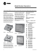
Model Number Description U H S B A 1 8 1 T A A 1 0 1 A 0 A 0 A 1 1 2 3 4 5 6 7 8 9 10 11 12 13 14 15 16 17 18 19 20 Description Vertical hydronic unit heaters are designed for installation requiring down flow air delivery, offered in 15 sizes ranging from 41,300 to 705,000 BTU/Hr., and use with steam or hot water. Low output (increased airflow) units are available for high ceiling applications.The designs are certified by CSA (per CAN/CSA-C22.2 and UL1995).
Model Number Description 180 204 240 280 300 360 180,000 BTU/HR 204,000 BTU/HR 240,000 BTU/HR 280,000 BTU/HR 300,000 BTU/HR 360,000 BTU/HR DIGIT 8—VOLTAGE 1 3 4 5 6 7 115/1/60 230/1/60 (115 V motor with Transformer) 208/3/60 230/3/60 460/3/60 575/60/3 (Totally Enclosed) (P only) DIGIT 17 - Manual Starter 0 A None Manual Starter DIGIT 18 - STEAM & HOT WATER CONTROL 0 1 2 3 4 None Strap on Hot Water Control Steam Pressure Control (Open on rise in pressure) Steam Pressure Control (Close on rise in pres
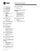
Location It is assumed that the design engineer has selected, sized, and located in the area to be heated. However, the information given here may be of additional help to the installer. These sketches indicate suggested basic locations for different types of unit heaters. Horizontal unit heaters should be located to give a circulatory motion, preferably in the outer perimeter of the building. The units should be spaced to properly blanket the areas with warm air. Figure 5.
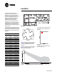
Location A UNIT SIZE 048/060 1-3/4 C 1" A B 15-5/16 1-7/8 2-1/2 072 16-9/16 084 & 120 19-1/16 3" 096/108 17-13/16 2-1/2 132/144/156 21-9/16 3-1/2 180/204 22-13/16 4" 240/280 26-1/16 4-1/2 300/360 31-9/16 6" C 11-11/16 10" C B B CL 1-3/4 4 PT. SUSPENSION USE 3/8-16 THREADED RODS (4 LOCATIONS) CL D6340 Figure 9.
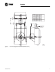
Location K OC C ET P M E ST T) N VE Y (S VE AL V TE GA "FORCED HOT WATER" RN TU RE LY PP SU E LV A EV T GA E D-6056 LV AIN VA DR Figure 10.
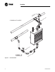
Location PET COCK (SYSTEM VENT) RE TU RN GATE VALVE SU PP LY "FORCED HOT WATER" (Serpentine Units) GATE VALVE DRAIN VALVE D-6057 Figure 11.
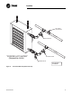
Location E LV E AT VA G "HIGH PRESSURE STEAM" PI TC H UP LY PP SU N UR T RE VE AL V TE GA CK PI T PE TC H UP D-6058 P RA ) T T ASS E P CK BY BU H AIR IT (W Figure 12.
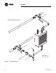
Location E LV A EV T "LOW PRESSURE STEAM GRAVITY" GA PI TC H UP Y PL P SU RN TU RE /4 NT AIR PI IZ .S N MI D-6059 TC VE TE E3 VE L VA H GA UP 10 "M IN .( VE K EC L VA 25 4M M) CH Figure 13.
Location E LV A EV T GA "LOW PRESSURE VAPOR OR VACUUM" PI TC H UP LY PP SU N UR T RE VE AL V TE GA PI TC H UP D-6060 ER P RA F Figure 14.
Installation Installation: P Type Periodic Service WARNING Heavy Objects! Ensure that all hardware used in the suspension of each unit heater is more than adequate for the job. Failure to do so may result in extensive property damage, severe personal injury or death.
Installation Table 3. Maximum Mounting Height in Feet with and without Louver Cone Diffuser Unit Size 042 042* 042L 042L* 064 064* 064L 064L* 080 080* Steam Pressure (PSI) Unit Size Steam Pressure (PSI) 2 (13.8) 5 (34.5) 10 (68.9) 50 (344.7) 75 (517.1) 2 (13.8) 5 (34.5) 10 (68.9) 50 (344.7) 75 (517.1) 10.5 (3.2) 10.0 (3.0) 10.0 (3.0) 9.0 (2.7) 8.0 (2.4) 18.0 (5.5) 17.5 (5.3) 17.5 (5.3) 15.0 (4.6) 14.0 (4.3) 12.5 (3.8) 12.0 (3.7) 12.0 (3.7) 11.0 (3.4) 10.0 (3.0) 22.
Installation Table 4. Maximum Mounting Height in Feet with and without Louver Cone Diffuser Steam Pressure (PSI) Unit Size 166 166L 202 202L 252 252L 280 280L 336 Steam Pressure (PSI) 2 (13.8) 5 (34.5) 10 (68.9) 50 (344.7) 75 (517.1) 18.0 (5.5) 17.5 (5.3) 17.0 (5.2) 14.5 (4.4) 14.0 (4.3) 22.5 (6.9) 22.0 (6.7) 21.5 (6.6) 19.0 (5.8) 18.0 (5.5) 22.0 (6.7) 21.5 (6.6) 21.0 (6.4) 18.5 (5.6) 17.5 (5.3) 27.5 (8.4) 27.0 (8.2) 26.5 (8.1) 23.5 (7.2) 22.5 (6.9) 22.0 (6.7) 21.
Installation Table 6. Maximum Mounting Height and Diameter at Floor (Based on 60°F EAT and 219°F EWT or 2 psig steam) Diffuser Cone 90° See Figure 5A Standard 16 Diffuser Cone 45° See Figure 5B Low Output Standard Low Output H D H D H D H D Model ft (m) ft (m) ft (m) ft (m) ft (m) ft (m) ft (m) ft (m) 42 12.5 (3.8) 11.0 (3.4) 14.5 (4.4) 16.0 (4.9) 9.0 (2.7) 20.0 (6.1) 11.0 (3.4) 25.0 (7.6) 64 14.5 (4.4) 12.0 (3.7) 19.0 (5.8) 19.0 (5.8) 10.0 (3.0) 24.0 (7.3) 12.0 (3.
Installation Figure 15. Notes: To meet OSHA requirements, units mounted lower than 8 feet from the floor must be equipped with an OSHA fan guard. Table 7. Mounting Height Correction Factors Water Temperature Steam Pressure °F 150 160 170 180 190 200 (°C) (66) (71) (77) (82) (88) (93) PSI - - - - - - (kPa) - - - - - - 1.32 1.27 1.23 1.18 1.14 1.
Installation Piping To provide proper coil operation, follow all piping recommendations listed in this manual. Threaded pipe headers are provided on all Vertical Units for piping connections. See Figure 25. Connections are given in Figure 18 and Figure 19 and Table 27 and Table 28. Follow standard practices and codes when installing the piping.
Installation Figure 18. Figure 19.
Installation Installation: S Type Unit Mounting WARNING at four points. Refer to Figure 20 and Figure 21 for two point suspension and refer to Figure 9 for four point suspension. Ensure that all hardware used in the suspension of each unit heater is more than adequate for the job. Failure to do so may result in extensive property damage, severe personal injury or death. Nutserts are provided at the top of all units for suspension purposes.
Fan Guard/Louver Installation OSHA Fan Guard/Louver Cone Diffuser Installation Detail WARNING Hazardous Voltage Do not mount either the Louver Cone Diffuser or OSHA Fan Guard while unit is in operation or severe personal injury may occur. Disconnect all power supplies to the unit before installing the Louver Cone Diffuser or OSHA Fan Guard. The figures below show how both the OSHA Fan Guard and the Louver Cone Diffuser are installed on the Vertical Steam and Hot Water Unit Heater.
Fan Guard/Louver Installation Figure 22. Vertical Unit with Louver Cone Diffuser Figure 23.
Dimensional Data Dimensional Data: P Model H H K K V G A R R G R A (4) MOUNTING HOLES 3 /8 - 16 FOR 42P-80P THREAD TAPS CEILING P L F T STEAM SUPPLY OR HOT WATER RETURN B S STEAM RETURN OR HOT WATER SUPPLY C T E P D Figure 24. Table 8. Models 42-80 Roughing in Dimensional Data - Model Size 42-80 Unit Capacity (MBH) Fan Dia.
Dimensional Data K H H V A K U V R G R A (4) MOUNTING HOLES 3/8 - 16 FOR 102P-384P THREAD TAPS 1/2 - 13 FOR 500P-720P CEILING P STEAM SUPPLY OR HOT WATER RETURN L F T B S C STEAM RETURN OR HOT WATER SUPPLY T E P D Figure 25. Table 9. Models 102-720 Roughing in Dimensional Data - Model Size 102-720 Unit Capacity (MBH) Fan Dia. 102 16 3/4 25 1/4 6 1/8 2 122 16 3/4 25 1/4 6 1/8 2 146 24 L (Min.
Dimensional Data Dimensional Data: S Model Figure 26. Note: Serpentine Type Models A08, A18, A25, A36 Motors are totally enclosed, thermally protected, sleeve bearing, with 4" (w) x 2" (h) conduit connection boxes. 3/8-16 nutserts are attached to enclosure for balanced hanging. Table 10. Table 3- Serpentine Models MODEL H inches (mm) W inches (mm) A inches (mm) B inches (mm) C inches (mm) NO. OF LOUVERS A08 16 (406) 18 (457) 16 7/32 (412) 11 1/4 (286) 4 1/4 (108) 5 9 (229) 22 (10.
Dimensional Data Figure 27. Note: 26 Header Type Models 18 thru 360 Motors are totally enclosed, thermally protected, sleeve bearing, with 4" (w) x 2" (h) conduit connection boxes. 3/8-16 nutserts are attached to enclosure for balanced hanging.
Dimensional Data Table 11. Header Models A B C D E F G* inches inches inches inches inches inches inches MODEL (mm) (mm) (mm) (mm) (mm) (mm) (mm) NO. H* J K L M N OF inches inches inches inches inches inches LOU(mm) (mm) (mm) (mm) (mm) (mm) VERS NOM. FAN APPROX. DIAM. SHIP inches WT. lbs. (mm) (kg) 18 14 5/8 (371) 7 5/16 (186) 15 (381) 7 1/2 (191) 6 1/8 2 15/16 (156) (75) 3 1/4 (83) 9 3/8 (238) 12 1/4 9 1/2 (311) (241) 1 1/4 (32) 2 1/4 12 7/8 (57) (327) 4 9 (229) 26 (11.
Technical Data Technical Data: S Models The performance data listed in Table 11 includes sound ratings. The ratings provide a guide in determining the acceptable degree of loudness in particular occupancy situations. Certain general rules apply to specific selection of unit heaters with regard to degree of quietness (or loudness); • The greater the fan diameter, the higher the sound level. • The higher the motor RPM, the higher the sound level.
Technical Data Technical Data: P Model Category of Area Sound Rating The performance data listed in Table 13, Table 14, and Table 15 include sound ratings. The ratings provide a guide in determining the acceptable degree of loudness in particular occupancy situations.
Options Options: S Models Variable Speed Control 115 Volt Only (optional) The solid state speed controller may be installed at any convenient location and is suitable for surface or flush type mounting. A Standard electrical single or double gang wall box is recommended as in Figure 28. 3. Mount face plate with screw provided and attach control knob. Strap-On Water Control A SPDT strap-on type hot water control with 100° to 240°F (38 to 116°C) rated at 10 amps at 120V is also available.
Options Options: P Models Variable Speed Control 115 Volt Only (optional) The solid state speed controller may be installed at any convenient location and is suitable for surface or flush type mounting. A standard electrical single or double gang wall box is recommended as in Figure 30. diffuser to the bottom of the unit heater as shown in Figure 51. Mounting holes are provided in the unit base plate. speeds indefinitely controllable.
Electrical Connections Electrical Connections: P Model cold air unless the heater has steam passing through the coil. WARNING Small hot water systems could have the circulating pump controlled directly by the room thermostat. On large systems, zone valves could be used to control the individual unit heater where constant water circulation is used on the main system. Hazardous Voltage Disconnect all electric power including remote disconnects before servicing.
Electrical Connections Figure 35. Fan Motor Connections 115/1/60 Constant Speed, Two Lead (GE, Marathon, Universal) Figure 32. Fan Motor Connections Low Voltage with Protector Select Rotation (CCW shown)(Marathon) For CW Rotation Interchange (Red and black lead) Figure 34. Fan Motor Connections Low Voltage CCW Internal (Marathon) Figure 33.
Electrical Connections Wiring Installation: P Model 1 PHASE LINE 3 PHASE LINE Notice 1. When using a speed controller, always locate the thermostat between the speed controller and the line, not between the motor and the controller. 2. For internal wiring and overload protection on all starters, consult the control manufacturer for details. 3. When using thermostatic control with a manual starter, be sure that the electrical rating of the thermostat is sufficient to carry the motor current.
Electrical Connections Electrical Connections: S Model WARNING 3 PHASE LINE MANUAL STARTING SWITCH THERMOSTAT LIMIT CONTROLLER REVERSE ACTING WARNING MOTOR MANUAL CONTROL WITH THREE PHASE MOTOR Figure 44. 1 PHASE LINE MANUAL STARTER WITH BUILT IN SELECTOR SWITCH THERMOSTAT LIMIT CONTROLLER MOTOR THREE POSITION SELECTOR SWITCH BUILT INTO MAGNETIC STARTER FOR MANUAL OR THERMOSTATIC CONTROL Figure 45.
Electrical Connections Wiring Installation: S Model 1 PHASE LINE 3 PHASE LINE Notice 1. When using a speed controller, always locate the thermostat between the speed controller and the line, not between the motor and the controller. 2. For internal wiring and overload protection on all starters, consult the control manufacturer for details. 3. When using thermostatic control with a manual starter, be sure that the electrical rating of the thermostat is sufficient to carry the motor current.
Electrical Connections 3 PHASE LINE MANUAL STARTING SWITCH THERMOSTAT LIMIT CONTROLLER REVERSE ACTING MOTOR MANUAL CONTROL WITH THREE PHASE MOTOR Figure 55. 1 PHASE LINE MANUAL STARTER WITH BUILT IN SELECTOR SWITCH THERMOSTAT LIMIT CONTROLLER MOTOR THREE POSITION SELECTOR SWITCH BUILT INTO MAGNETIC STARTER FOR MANUAL OR THERMOSTATIC CONTROL Figure 56.
Motor Data Motor Data: P Models CAUTION Voltage Selections Select appropriate AMP, MCA, and MOP for the multiple voltage motors. For example, the AMP, MCA, and MOP for Model 40 with a 230 volt Totally Enclosed motor is 1.1, 1.4, and 2.5 respectively. Note: Note: All motors are constant speed and operate at top speed as indicated in motor data. Models through 1/8 H.P. can be run at reduced speed with addition of optional variable speed switch.
Motor Data in motor data. All 1/4 H.P. motors are P.S.C. Table 17. Explosion Proof with Thermal Overload Motor Type [MT=2] Unit Model No. AMP MCA MOP HP RPM Note: Motors under 1/3 H.P. are totally enclosed, frame mounted, 115/1/60 with thermal overload protection and permanently lubricated sleeve bearings with optional speed controller available. 1/3 H.P. (115/1/60) motors are open frame constant speed with thermal over-load protection and ball bearings. 1/3 H.P. (230V) and 1/2 H.P.
Motor Data Table 18. Totally Enclosed Motor Type Unit Model No. AMP MCA MOP HP RPM 115/1/60 18, 24, A08, A18 0.8 1 1.8 16W* 1550 A36 1.4 1.8 3.2 1/20* 1000 36, A25 1.2 1.5 2.7 25W* 1550 48, 60, 72 1.4 1.8 3.2 1/20* 1000 84, 96, 108 2.2 2.8 5.0 1/12* 1000 120, 132, 144, 156, 180, 204, 240 4.5 5.6 10.1 1/3 1140 280, 300, 360 5.4 6.8 12.2 1/2 1100 230/1/60 18, 24, A08, A18 0.4 0.5 0.9 16W 1550 A36 1.4 1.8 3.2 1/20† 1000 36, A25 0.6 0.8 1.
Steam Performance Data Table 20. Unit Size Model S Header Type Only Output BTU/ HR* (kW) Cond. E.D.R. Final Air lbs./hr. Sq. Ft. Deg. °F Motor HP (kg/hr) (sq. m) (Deg. °C) (kW) 18,000 (5.3) 18.0 (8.2) 75 (7.0) 102 (39) 16,200 (4.7) 16.2 (7.3) 68 (6.3) 105 (41) 24,000 (7.0) 24.5 (11.1) 100 (9.3) 109 (43) 21,600 (6.3) 22.0 (10.0) 90 (8.4) 112 (44) 36,000 (10.5) 37.0 (16.8) 150 (13.9) 119 (48) 32,400 (9.5) 33.0 (14.9) 135 (12.5) 120 (49) 48,000 (14.1) 49.0 (22.2) 200 (18.
Steam Performance Data Table 20. Model S Header Type Only (continued) Output BTU/ HR* (kW) Cond. E.D.R. Final Air lbs./hr. Sq. Ft. Deg. °F Motor HP (kg/hr) (sq. m) (Deg. °C) (kW) 280 280,000 (82.0) 280.0 (126.8) 1100 (102.2) 121 (49) 1/2 (.373) 1100 4200 (1.982) 980 (4.978) 5.4 20 (508.0) 300 300,000 (87.9) 310.0 (140.4) 1250 (116.1) 117 (47) 1/2 (.373) 1100 5000 (2.360) 700 (3.556) 5.4 24 (609.6) 360 360,000 (105.5) 366.0 (165.8) 1500 (139.4) 120 (49) 1/2 (.
Steam Performance Data Table 23. PROPERTIES OF SATURATED STEAM STEAM PRESSURE IN PSIG (kPa) Steam Pressure psi (kPa) Steam Temperature Deg. F (Deg. C) 0 (0) 2 (13.8) 5 (34.5) 10 15 20 30 40 50 75 100 125 150 (68.9) (103.4) (137.9) (206.8) (275.8) (344.7) (517.1) (689.4) (891.8) (1,034.1) 212 218.5 227.1 239.4 249.8 258.8 274.0 286.7 297.7 319.9 337.9 352.9 365.9 (100) (103.6) (108.4) (115.2) (121.0) (126.0) (134.4) (141.5) (147.6) (159.9) (169.9) (178.3) (185.
Steam Performance Data Table 25. "Low Output" Standard Vertical Units with All Air Ports Open Unit Output Condensate E.D.R. Final Air Capacity BTU/HR lbs./hr Sq. ft. Temp. °F Motor H.P. Motor Nominal Outlet Velocity FPM (m/s) Sound Rating (MBH) (kW) (kg/hr) (Sq. m) °C (kW) RPM CFM (m3/s) 042L 34,800 (10.2) 36 (16.3) 145 (13.5) 108 (42) 26,000 (7.6) 27 (12.2) 108 (10.0) 111 (44) 1/40 (.019) 1550 668 (.312) 950 (4.826) 1150 470 (.219) 672 (3.414) 1200 1190 (.560) (6.045) 862 858 (.
Steam Performance Data Table 26. STEAM CALCULATIONS AND CORRECTION FACTORS P STYLE EXAMPLE: UNIT SIZE __________ 042 Steam Pressure _____10 PSI Entering Air Temp. ____ 40°F I. CAPACITY A. For 2 lbs. steam, 60° entering air Read output directly from Table 24: 41,300 BTU/ HR. B. For higher steam pressures and/or E.A.T.'s above Multiply output from Table 24 by appropriate or below 60°F correction factor from Table 27. 41,300 x 1.27 = 52,451 BTU/HR. II. FINAL AIR TEMPERATURE A. For 2 lbs.
Hot Water Performance Data Table 29. Model S Serpentine and Header Type Output Final Air Prssr. Drop BTU/HR* Flow Rate Deg. °F FT./H2O Unit Size (kW) GPM (L/s) (Deg. °C) (m/water) Motor HP (kW) A08 A18 A25 A36 018 024 036 048 060 072 084 096 108 8,030 (2.4) 6,800 (2.0) 18,400 (5.4) 15,650 (4.6) 24,800 (7.3) 21,230 (6.2) 35,900 (10.5) 32,300 (9.5) 13,050 (3.8) 11,725 (3.4) 17,400 (5.1) 15,600 (4.6) 26,100 (7.6) 23,500 (6.9) 34,800 (10.2) 31,300 (9.2) 43,600 (12.8) 39,200 (11.5) 52,300 (15.
Hot Water Performance Data Table 29. Model S Serpentine and Header Type (continued) 120 87,100 (25.5) 8.8 (.555) 102 (39) 0.39 (.119) 1/3 (.249) 1140 1900 (.897) 900 (4.572) 4.5 III 132 95,800 (28.1) 9.6 (.606) 104 (40) 0.41 (.125) 1/3 (.249) 1140 2000 (.944) 950 (4.826) 4.5 IV 144 104,000 (30.5) 10.4 (.656) 104 (40) 0.43 (.131) 1/3 (.249) 1140 2200 (1.038) 1000 (5.080) 4.5 IV 156 113,000 (33.1) 11.3 (.713) 100 (38) 0.53 (.162) 1/3 (.249) 1140 2600 (1.
Hot Water Performance Data Table 31. HOT WATER CONVERSION FACTORS BASED ON 200° (93°C) ENTERING WATER, 60° (16°C) ENTERING AIR AND 20° (11°C) TEMPERATURE DROP ENTERING AIR TEMPERAT URE °F (°C) ENTERING WATER TEMPERATURE - °F (°C) 100° (38) 120° (49) 140° (60) 160° (71) 180° (82) 200° (93) 220° (104) 240° (116) 260° (127) 280° (138) 300° (149) 30 -(1) 0.518 0.666 0.814 0.963 1.120 1.268 1.408 1.555 1.702 1.850 1.997 40 (4) 0.439 0.585 0.731 0.878 1.025 1.172 1.317 1.464 1.
Hot Water Performance Data Table 35. P Type Standard Output Units** Final Water Air. Nominal Temp. Press. Drop Outlet Temp. CFM Drop Output MBH Flow Rate ft/water Velocity (kW) G.P.M. (L/s) (m/water) °F (°C) Motor H.P. (kW) R.P.M. (m3/s) FPM (m/s) Model No. °F (°C) 42 42* 64 64* 80 80* 102 102* 122 10° (5.6°) 28.8 (8.4) 5.93 (.374) .37 (.113) 104.6° (40.3°) 20° (11.1°) 22.7 (6.7) 2.34 (.148) .06 (.018) 95.2° (35.1°) 30° (16.7°) 16.7 (4.9) 1.15 (.073) .02 (.006) 85.9° (29.
Hot Water Performance Data Table 35. P Type Standard Output Units** (continued) Water Final Temp. Press. Drop Air. Nominal Outlet Drop Output MBH Flow Rate ft/water Temp. CFM Velocity Model No. °F (°C) (kW) G.P.M. (L/s) (m/water) °F (°C) Motor H.P. (kW) R.P.M. (m3/s) FPM (m/s) 146 166 202 252 280 336 384 500 600 50 10° (5.6°) 117.6 (34.5) 24.24 (1.529) 4.32 (1.318) 108.8° (42.7°) 20° (11.1°) 105.2 (30.8) 10.84 (.684) .96 (.293) 103.7° (39.8°) 30° (16.7°) 92.8 (27.2) 6.38 (.402) .
Hot Water Performance Data Table 35. P Type Standard Output Units** (continued) Water Final Temp. Press. Drop Air. Nominal Outlet Drop Output MBH Flow Rate ft/water Temp. CFM Velocity Model No. °F (°C) (kW) G.P.M. (L/s) (m/water) °F (°C) Motor H.P. (kW) R.P.M. (m3/s) FPM (m/s) 720 20° (11.1°) 519.4 (152.2) 53.52 (3.376) 5.29 (1.613) 103.5° (39.7°) 30° (16.7°) 470.9 (138.0) 32.35 (2.041) 2.08 (.634) 99.5° (37.5°) 3 (2.237) 1165 11,000 (5.133) 2250 (11.
Hot Water Performance Data Table 36. Low Output Units Standard Vertical Unit with All Air Ports Open** (continued) Water Temp. Press. Drop Drop Output MBH Flow Rate ft/water Model No. °F (°C) (kW) G.P.M. (L/s) m/water 102L* 122L 146L 166L 202L 252L 280L 336L 384L 52 Final Air. Nominal Outlet Temp. CFM Velocity 3 °F (°C) Motor H.P. (kW) R.P.M. (m /s) FPM (m/s) Sound Rating 10° (5.6°) 54.5 (16.0) 11.24 (.709) 1.06 (.323) 93.5° (34.2°) 20° (11.1°) 48.5 (14.2) 4.99 (.315) .23 (.070) 89.
Hot Water Performance Data Table 36. Low Output Units Standard Vertical Unit with All Air Ports Open** (continued) Water Temp. Press. Drop Drop Output MBH Flow Rate ft/water Model No. °F (°C) (kW) G.P.M. (L/s) m/water 500L 600L 720L Final Air. Nominal Outlet Temp. CFM Velocity 3 °F (°C) Motor H.P. (kW) R.P.M. (m /s) FPM (m/s) Sound Rating 20° (11.1°) 310.5 (91.0) 32.00 (2.019) 4.23 (1.290) 90.5° (32.5) 30° (16.7°) 281.7 (82.5) 19.35 (1.221) 1.67 (.509) 87.7° (30.9) 10° (5.6°) 394.4 (115.
Hot Water Performance Data Table 38. HOT WATER CONVERSION FACTORS BASED ON 200° ENTERING WATER 60° ENTERING AIR 20° TEMPERATURE DROP ENTERING WATER TEMPERATURE -20° WATER TEMPERATURE DROP ENTERING AIR TEMPERATURE °F (°C) 100° (38°) 30° (-1) 0.518 0.666 0.814 40° (4) 0.439 0.585 0.731 50° (10) 0.361 0.506 0.651 60° (16) 0.286 0.429 70° (21) 0.212 80° (27) 0.
Maintenance Periodic Service WARNING Hazardous Voltage Open all disconnect switches and secure in that position before servicing unit. Failure to do so may result in personal injury or death from electrical shock. CAUTION Rotating Components Allow rotating fans to stop before servicing to avoid serious injury to fingers and hands. Because of the simple design of the steam and hot water unit heaters, they are nearly maintenance free.
Maintenance Table 42. Troubleshooting Guide Symptoms Possible Cause(s) Corrective Action A. Leaking coil 1. 2. 3. 4. B. Poor output on steam 1. Check for air in coil. 2. Lint on coil fins 1. Repair or replace thermostatic air vent. 2. Clean coil and fins. Check filter and clean. C. Poor output on steam or hot water 1. No circulation of water through coil. 2. Short cycling of motor. 3. Backward rotating motor. 1. Check circulation pump. Check for blocked tubes. 2. Check voltage and correct.
Warranty Info LIMITED WARRANTY: S Model HORIZONTAL STEAM & HOT WATER UNIT HEATERS The Manufacturer warrants to the original owner at the original installation site that the Horizontal Steam and Hot Water Unit Heaters (the “Product”) will be free from defects in material and workmanship for a period not to exceed one (1) year from startup or eighteen (18) months from date of shipment from the factory, whichever occurs first.
Warranty Info SELLING PRICE OF THE PRODUCT OR ANY PARTS THEREOF FOUND TO BE DEFECTIVE. THIS LIMITED WARRANTY GIVES THE ORIGINAL OWNER OF THE PRODUCT SPECIFIC LEGAL RIGHTS. YOU MAY ALSO HAVE OTHER RIGHTS WHICH MAY VARY BY EACH JURISDICTION.
Trane A business of American Standard Companies www.trane.com For more information, contact your local Trane office or e-mail us at comfort@trane.com Literature Order Number UH-SVX01A-EN Date 05/07 Supersedes UH-IM-2F (09/99) Trane has a policy of continuous product and product data improvement and reserves the right to change design and specifications without notice.