Installation, Operation, and Maintenance Series R® Air-Cooled Helical Rotary Liquid Chillers SAFETY WARNING Only qualified personnel should install and service the equipment. The installation, starting up, and servicing of heating, ventilating, and air-conditioning equipment can be hazardous and requires specific knowledge and training. Improperly installed, adjusted or altered equipment by an unqualified person could result in death or serious injury.
Introduction Read this manual thoroughly before operating or servicing this unit. Warnings, Cautions, and Notices Safety advisories appear throughout this manual as required.Your personal safety and the proper operation of this machine depend upon the strict observance of these precautions. The three types of advisories are defined as follows: Indicates a potentially hazardous situation which, if not avoided, could result in death or serious injury.
Introduction Factory Warranty Information Compliance with the following is required to preserve the factory warranty: All Unit Installations Startup MUST be performed byTrane, or an authorized agent ofTrane, to VALIDATE this WARRANTY. Contractor must provide a two-week startup notification toTrane (or an agent ofTrane specifically authorized to perform startup).
Table of Contents Introduction . . . . . . . . . . . . . . . . . . . . . . . . . . . . . 2 Table of Contents . . . . . . . . . . . . . . . . . . . . . . . . 4 Model Number Description . . . . . . . . . . . . . . . Outdoor Unit Nameplate . . . . . . . . . . . . . . . Compressor Nameplate . . . . . . . . . . . . . . . . Unit Model Number . . . . . . . . . . . . . . . . . . . . Compressor Model Number . . . . . . . . . . . . Compressor Serial Number . . . . . . . . . . . . . 6 6 6 7 8 8 General Data . . . .
Table of Contents (Programmable Relays) . . . . . . . . . . . . . . . 68 TechView . . . . . . . . . . . . . . . . . . . . . . . . . . . . .83 Relay Assignments Using TechView . . . . 69 Unit View . . . . . . . . . . . . . . . . . . . . . . . . . .85 Low Voltage Wiring . . . . . . . . . . . . . . . . . . . 69 Compressor Service View . . . . . . . . . . . . .85 Emergency Stop . . . . . . . . . . . . . . . . . . . . 69 Status View . . . . . . . . . . . . . . . . . . . . . . . . .85 External Auto/Stop .
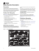
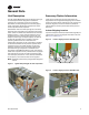
Model Number Description Nameplates of typical unit model number and the coding system for each. The RTAC outdoor unit nameplates are applied to the exterior of the Control Panel. A compressor nameplate is located on each compressor. When the unit arrives, if unit is not covered with a tarp, compare all nameplate data with ordering, submittal, and shipping information. Each position, or group of positions, in the model number is used to represent a feature.
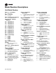
Model Number Descriptions Unit Model Number Digits 1, 2 - Unit Model Digit 15 - Evaporator Application Digit 25 - Control Input Accessories/Options F G = = N R = = Digit 4 - Development Sequence R = C Digit 16 - Evaporator Configuration C B = = RT = Rotary chiller Digit 3 - Unit Type A = = Air-cooled Development sequence Digits 5, 6 & 7 - Nominal Capacity 120 130 140 155 170 185 200 225 250 275 300 350 375 400 450 500 = = = = = = = = = = = = = = = = 120 Nominal tons 130 Nominal tons 140
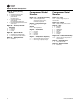
Model Number Descriptions Digit 34 - Factory Testing Options 0 C = = C = E = Standard functional test Customer-witnessed performance test with report Customer-witnessed performance test plus Rapid Restart test Non-witnessed performance test with report Digit 35 — Control, Label & Literature C E F = = = Spanish English French Digit 36 — Special Order X S = = Standard unit configuration Unit has special order feature Digit 37 — Safety Devices N = Standard Compressor Model Number Compressor Se
General Data Unit Description Accessory/Option Information The 140 - 500 ton Model RTAC units are helical-rotary type, air-cooled liquid chillers designed for installation outdoors.The compressor circuits are completely assembled, hermetic packages that are factory-piped, wired, leak-tested, dehydrated, and tested for proper control operation before shipment. Check all the accessories and loose parts which are shipped with the unit against the shipping list.
General Data Table 1.
General Data Table 2.
General Data Table 3.
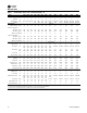
General Data Table 4. General Data - 60 hz units - standard efficiency - SI Size 140 155 170 185 200 225 250 275 Compressor Quantity # Nominal size (tons) @60Hz 2 70/70 2 85/70 2 2 2 100/ 85/85 100/85 100 2 2 120/ 100 120/ 120 350 400 450 500 3 3 3 4 4 4 85-85/ 100-100/ 120-120/ 100-100/ 120-120/ 120-120/ 100 100 100 100-100 100-100 120-120 Evaporator Water storage 300 Screw Flooded (L) 110.
General Data Table 5.
General Data Table 6.
General Data Table 7.
General Data Table 8.
General Data Table 9.
General Data Table 10.
Pre-installation Unit Inspection When unit is delivered, verify it is the correct unit and is properly equipped. • • If unit is covered with optional tarp, confirm unit was ordered with a tarp. Inspect tarp for any visible damage. If unit does not have optional tarp, compare information on unit nameplate with ordering and submittal information. Inspect all exterior components for visible damage.
Dimensions and Weights Dimensions See unit submittals for specific unit dimensions and water connection locations. Clearances Provide enough space around the outdoor unit to allow the installation and maintenance personnel unrestricted access to all service points. Refer to submittal drawings for the unit dimensions. A minimum of 4 feet (1.2 m) is recommended for compressor service. Provide sufficient clearance for the opening of control panel doors. See Figure 5, p. 21 through Figure 9, p.
Dimensions and Weights Figure 7. Recommended unit clearances 30-45 foot bases Tube Removal Clearance Area (Non DynaView Control Panel End) Figure 8.
Dimensions and Weights Figure 9. Recommended evaporator clearance 148” (3760 mm) Unobstructed flow of condenser air is essential to maintain chiller capacity and operating efficiency. When determining unit placement, give careful consideration to assuring a sufficient flow of air across the condenser heat transfer surface.Two detrimental conditions are possible and must be avoided if optimum performance is to be achieved: warm air recirculation and coil starvation.
Dimensions and Weights Weights Non-Seismically Rated Units Table 11.
Dimensions and Weights Table 13.
Dimensions and Weights Seismically Rated Unit Weights Table 15.
Dimensions and Weights Remote Evaporator Unit Weights Table 16.
Installation - Mechanical Location Requirements Rigging Noise Considerations Lifting Procedure Locate outdoor unit away from sound sensitive areas. If required, install rubber vibration isolators in all water piping and use flexible electrical conduit. Consult an acoustical engineer for critical applications. Also refer to Trane Engineering Bulletins for application information on RTAC chillers.
Installation - Mechanical Rigging See Figure 10 through Figure 12, p. 29 for lifting point references, Table 19 through Table 21 for lifting weights, and unit submittals lift point dimensions. Figure 10. Lifting the unit (packaged and remote) 15-21 foot base Figure 11. Lifting the unit (packaged and remote) 30-36 foot base Control Panel W1 - near side W2 - far side W3 - near side W4 - far side W5 - near side W6 - far side Figure 12.
Installation - Mechanical Figure 13. Lifting the remote evap W1 - Near Side W2 - Far Side W3 - Near Side W4 - Far Side 25” (625mm) 30” (762mm) SIDE VIEW Lifting Weights Tables Table 18.
Installation - Mechanical Table 19. Size (tons) Lifting weights (lbs) - packaged units - 50 Hz Table 20.
Installation - Mechanical Table 21.
Installation - Mechanical Center of Gravity Table 23. Unit Size (tons) Table 23. Center of gravity (in) - 60 Hz Packaged X Y Z Remote X Y Remote Evap Z X Y Z Aluminum Coils - Standard Efficiency 140 88 45 35.5 85 45 37.25 39 30 25 155 88 45 35.5 85 45 37.25 39 30 25 170 88 45 35.5 85 45 37.25 39 30 25 185 106 44 35.5 103 44 39 53 30 25 200 106 45 35.5 107 45 39 53 30 25 225 124 45 35.5 121 45 41.5 53 30 25 250 124 45 35.
Installation - Mechanical Isolation and Sound Emission Mounting and Leveling The most effective form of isolation is to locate the unit away from any sound sensitive area. Structurally transmitted sound can be reduced by elastomeric vibration eliminators. Spring isolators are not recommended for non-seismically rated applications. Consult an acoustical engineer in critical sound applications.
Installation - Mechanical Unit Isolation for Seismically Rated Units Seismic Elastomeric Isolation Pads Elastomeric pads are provided with an isolation washer and 3/4” free hole in the center of the plate. Isolation pads are shipped inside the unit control panel. See Table 26 for pad specifications. Table 26. Seismically rated elastomeric isolation pad Set isolation pads on mounting surface, ensuring that all isolator centerlines match the submittal drawing.
Installation - Mechanical Seismic Spring Isolators See “Seismic Isolator Mounting,” p. 44 for mounting locations, isolator selection and point weights. Seismically rated isolators are optional for IBC and OSHPD seismically rated units. Install the optional seismically rated isolators at each mounting location specified in section “Seismic Isolator Mounting,” p. 44. Figure 17. MSSH Seismic isolator installation reference Table 28.
Installation - Mechanical 6. Back off each of the (2) or (4) limit stop locknuts (F) per isolator 1/4-3/8”. 7. Adjust each isolator in sequence by turning adjusting nut(s) (G) one full clockwise turn at a time. Repeat this procedure on all isolators, one at a time. check the limit stop locknuts (F) periodically to ensure that clearance between the washer and rubber grommet is maintained. Stop adjustment of an isolator only when the top plate (A) has risen just above the shim (E). 8.
Installation - Mechanical Elastomeric Isolator Selection Table 31.
Installation - Mechanical Table 32.
Installation - Mechanical Point Weights (Units without Seismic Rating) See Table 34, p. 40 through Table 36, p. 43 for point weights of units that are NOT seismically rated. Table 34. Size (tons) See Table 40, p. 46 for seismically rated units (unit model number digit 13 = S or E).
Installation - Mechanical Table 34.
Installation - Mechanical Table 35.
Installation - Mechanical Table 36.
Installation - Mechanical Seismic Isolator Mounting Figure 19. Mounting locations — seismic spring isolators or seismic elastomeric pads B CONTROL PANEL (CKT 1 PANEL) A Table 37. Size (tons) C D C G 1.19” 4 6 8 10 12 14 1 3 5 7 9 11 13 Table 38. Dimension (in) B F 2 Mounting locations — 60 Hz units with seismic rating A E D E F G Size (tons) 1.
Installation - Mechanical Seismic Spring Isolator Selection Table 39.
Installation - Mechanical Point Weights (Units with Seismic Rating) Table 40.
Installation - Mechanical Drainage Evaporator Water Piping Provide large capacity drain for use during shutdown or repair. Evaporator is provided with drain connection. All local and national codes apply. Vent on top of evaporator waterbox prevents vacuum by allowing air into evaporator for complete drainage. RTAC units are available with 2- or 3-pass evaporator configurations. Figure 20.
Installation - Mechanical Thoroughly flush all water piping to the unit before making the final piping connections to the unit. Components and layout will vary slightly, depending on the location of connections and the water source. NOTICE: Evaporator Damage! The chilled water connections to the evaporator are to be “victaulic” type connections.
Installation - Mechanical Dirt, scale, products of corrosion and other foreign material will adversely affect heat transfer between the water and system components. Foreign matter in chilled water system can also increase pressure drop and reduce water flow. Proper water treatment must be determined locally, depending on system and local water characteristics. Neither salt nor brackish water is recommended. Use of either will lead to a shortened life to an indeterminable degree.
Installation - Mechanical Figure 23. Evaporator water pressure drop— 2-pass evaporator —120-250 ton 100.00 50.00 140S, 120H(50Hz) Pressure Drop ( H2O) Pressure Drop (ft H2O) 155S, 130H(50Hz) 170S, 140H 185S, 155H 200S, 170H 10.00 225S, 185H 250S(60Hz), 200H, 225H, 250H(60Hz) 5.00 1.00 100 200 300 400 500 700 1000 Flow Rate (GPM) Fl R t (GPM) Figure 24. Evaporator water pressure drop — 2-pass evaporator — 250-500 ton 100.00 50.
Installation - Mechanical Figure 25. Evaporator water pressure drop — 3-pass evaporator — 140-250T 100.00 50.00 140S, 120H(50Hz) Pressure Drop (ft H2O) 155S, 130H(50Hz) 170S, 140H 10.00 185S, 155H 200S, 170H 5.00 225S, 185H 250S(60Hz), 200H, 225H, 250H(60Hz) 1.00 200 100 300 400 500 600 700 Flow Rate (GPM) Figure 26. Evaporator water pressure drop — 3-pass evaporator — 250-500T 80.00 60.00 40.00 250S(50Hz) 20.00 275S Pressure Drop (ft H2O) 300S, 250H(50Hz) 350S(60Hz), 275H, 300H 10.
Installation - Mechanical Water Pressure Gauges Figure 27. Suggested piping for typical RTAC evaporator Flow Switch (Factory Installed) Install field-supplied pressure components as shown in Figure 27, p. 52. Locate pressure gauges or taps in a straight run of pipe; avoid placement near elbows, etc. Be sure to install the gauges at the same elevation on each shell if the shells have opposite-end water connections.
Installation - Mechanical Freeze Avoidance One or more of the ambient freeze avoidance methods in Table 41 must be used to protect the RTAC chiller from ambient freeze damage. Table 41. Note: A secondary set of pump interlock is strongly recommended, but not required. RTAC freeze avoidance methods Method Protects to ambient temperature Notes • Heaters alone will provide low ambient protection down to -20°F (-29°C), but will NOT protect the evaporator from freezing as a result of charge migration.
Installation - Mechanical 2. LRTC is 4 deg F below freeze point. Procedure 1. Is operating condition contained within Table 42, p. 54? If no, see “Specials,” p. 54. 2. For leaving fluid temperatures greater than 40 deg F, use settings for 40 deg F. 3. Select operating conditions from Table 42. 4. Read off recommended % glycol. 5. Go to Table 43, p. 55 using the % glycol determined above. Important: Additional glycol beyond the recommendations will adversely effect unit performance.
Installation - Mechanical Table 43. % Glycol Recommended low evaporator refrigerant cutout and percent glycol Low Refrig. Temp Cutout °F Solution Freeze Point °C °F °C Ethylene 0 28.0 -2.2 32 0 5 25.0 -3.9 29 -1.7 10 21.5 -5.8 25.5 -3.6 15 17.5 -8.1 21.5 -5.8 20 12.8 -10.7 16.8 -8.4 25 7.4 -13.7 11.4 -11.4 30 1.1 -17.2 5.1 -15.0 35 -5.0 -20.6 -2.3 -19.1 40 -5.0 -20.6 -10.8 -23.8 45 -5.0 -20.6 -20.7 -29.3 50 -5.0 -20.6 -32.1 -35.6 54 -5.0 -20.
Installation - Mechanical Remote Evaporator Option The RTAC 140-250 ton outdoor unit with the Remote Evaporator option is shipped as two pieces: the outdoor unit (condensing) and the evaporator. Short suction line connections are provided with the outdoor condensing unit.The remote evaporator is shipped complete, with factory-mounted electronic expansion valves, water temperature sensors, suction pressure transducers, liquid level control sensors, evaporator flow switch, all factory wired to a ribbon cable.
Installation - Mechanical Remote Evaporator Option line trap at the condensing unit is required to prevent unwanted free cooling.The apex of the liquid line trap should be at a height above the condenser coils. A suction accumulator must be installed at the evaporator. Refer to Table 46, p. 60 for sizing. and operation of the chiller, that the elevation requirements given in Table 44, p. 59 are not exceeded.
Installation - Mechanical Remote Evaporator Option Figure 29.
Installation - Mechanical Remote Evaporator Option Table 44. Liquid line sizing(a) - 140-250T remote evaporator Leaving water 40-50°F Height (ft) 0 1-5 6-10 Leaving water 50-60°F 11-15 16-20 21-25 26-30 31-35 Height (ft) 0 1-5 6-10 11-15 16-20 21-25 26-30 70-ton circuit 25 1.375 1.375 1.375 1.375 1.375 1.375 1.375 n/a 25 1.375 1.375 1.375 1.375 1.375 1.375 2.125 50 1.375 1.375 1.375 1.375 1.375 1.375 1.375 n/a 50 1.375 1.375 1.375 1.375 1.375 1.625 2.125 75 1.
Installation - Mechanical Remote Evaporator Option Line Sizing 3. See Table 44, p. 59 to determine outside diameter corresponding to equivalent length computed in step 2 for height and leaving water temperature of interest. To determine the appropriate outside diameter for field installed liquid and suction lines, it is first necessary to establish the equivalent length of pipe for each line. It is also necessary to know the capacity (tons) of each circuit.
Installation - Mechanical Remote Evaporator Option Example Liquid Line Sizing Figure 30. Liquid line sizing example The steps to compute suction line size are as follows: For this example, refer to Table 44, p. 59, Table 45, p. 60 and Figure 30, p. 61. Assume a 70 ton circuit and a leaving water temperature of 49 degrees F. 1. From Figure 30, p. 61, the actual length of field installed piping is: 80 + 8 + 8 + 21 = 117 feet 2. Estimate equivalent line length: 117 feet x 1.5 = 175 feet 3. From Table 44, p.
Installation - Mechanical Remote Evaporator Option 1. Use the 70 ton circuit column. 2. From the liquid line sizing example, use a field installed liquid line of: 1.375 (1 3/8”) inches 3. The actual feet of liquid line installed is: 117 feet 4. The size of the suction accumulator is: 3 5/8 inches 5.
Installation - Mechanical Remote Evaporator Option Table 48. Pressure Relief Valve Data Unit Sizes Valve Discharge Rated Capacity per Field Connection Pipe Factory Shell Side Location Setpoint (psi) Qty Valve (lba/min.) Size (NPT) Connection (in) 120H - 250S 60Hz/200H/170XE Evap 200 2 17.3 5/8 MFL 7/8 - 14 UNF-2A 250S 50Hz/225H/185XE - 500S Evap 200 2 28.9 3/4 NPTFI 7/8 - 14 UNF-2A All Oil Sep 350 2 6.
Installation - Mechanical Remote Evaporator Option Figure 32. Field wiring between remote evaporator and condensing unit Refrigerant and Additional Oil Charge Refrigerant Charge Determination without the field-installed piping. The approximate amount of refrigerant charge required by the system must be determined by referring to Table 49 and must be verified by running the system and checking subcooling. 2. Next, determine the charge required for the field-installed piping by referring to Table 49, p.
Installation - Electrical General Recommendations As you review this manual, keep in mind that: • All field-installed wiring must conform to National Electric Code (NEC) guidelines, and any applicable state and local codes. Be sure to satisfy proper equipment grounding requirements per NEC. • Compressor motor and unit electrical data (including minimum circuit ampacities, motor kW, voltage utilization range, rated load amps) is listed on the chiller nameplate.
Installation - Electrical Installer-Supplied Components Customer wiring interface connections are shown in the electrical schematics and connection diagrams that are shipped with the unit.The installer must provide the following components if not ordered with the unit: • Power supply wiring (in conduit) for all field-wired connections. • All control (interconnecting) wiring (in conduit) for field supplied devices. • Fused-disconnect switches or circuit breakers. • Power factor correction capacitors.
Installation - Electrical Figure 33. Control panel Incoming Customer Power Location Knockouts for 30V Cut holes for power wiring in THIS AREA See side view. 115V Field Wiring Side View - Right Figure 34. Single point power box - optional on dual panel units Incoming Customer Power Cut holes Location for power wiring in THIS AREA See side view.
Installation - Electrical NOTICE: Equipment Damage! Control panel main processor does not check for loss of power to the heat tape nor does it verify thermostat operation. A qualified technician must verify power to the heat tape and confirm operation of the heat tape thermostat to avoid catastrophic damage to the evaporator. A convenience outlet is also optional, which shares the same power supply as the heaters on 140-250 ton units.
Installation - Electrical likely needs, while only using four physical output relays, as shown in the field wiring diagram.The four relays are provided (generally with a Quad Relay Output LLID) as part of the Alarm Relay Output Option.The relay’s contacts are isolated Form C (SPDT), suitable for use with 120 VAC circuits drawing up to 2.8 amps inductive, 7.2 amps resistive, or 1/3 HP and for 240 VAC circuits drawing up to 0.5 amp resistive.
Installation - Electrical diagnostic.This condition requires manual reset at the chiller switch on the front of the control panel. Communicated input (Tracer) to initiate and command the Ice Building mode. Connect low voltage leads to terminal strip locations on 1U4. Refer to the field diagrams that are shipped with the unit. CH530 also provides a “Front Panel IceTermination Setpoint”, settable throughTechView, and adjustable from 20 to 31°F (-6.7 to -0.5°C) in at least 1°F (1°C) increments.
Installation - Electrical each correspond to a 10 to 65°F (-12 to 18°C) external chilled water setpoint. The following equations apply: Voltage Signal Current Signal As generated from external source VDC=0.1455*(ECWS)+ mA=0.2909(ECWS)+ 0.5454 1.0909 As processed by CH530 ECWS=6.875*(VDC)3.75 Depending on the type to be used, theTechView Service Tool must be used to configure the LLID and the MP for the proper input type that is being used.
Installation - Electrical and CWS' - CWS < or = Maximum Reset where CWS' is the new chilled water set point or the “reset CWS” Communications Interface Options CWS is the active chilled water set point before any reset has occurred, e.g. normally Front Panel,Tracer, or ECWS Tracer Communications Interface Option RESET RATIO is a user adjustable gain This option allows theTracer CH530 controller to exchange information (e.g.
Operating Principles refrigerants must be certified.The Federal Clean Air Act (Section 608) sets forth the requirements for handling, reclaiming, recovering and recycling of certain refrigerants and the equipment that is used in these service procedures. In addition, some states or municipalities may have additional requirements that must also be adhered to for responsible management of refrigerants. Know the applicable laws and follow them.
Operating Principles Condenser and Subcooler Condenser and subcooler are similar to the condenser used in RTAA chillers.The heat exchanger consists of 3/8” tubes that contain refrigerant, large fins that are in the air flow and fans that draw air through fins. Heat is transferred from the refrigerant through the tubes and fins to the air. High pressure gas from the compressor enters the tubes of the condenser through a distribution header (state 2b).
Controls Interface Overview languages as factory-ordered or can be easily downloaded from www.trane.com. RTAC units utilize theTracer™ CH530 chiller control system which consists of several elements: TechView can be connected to either the DynaView module and provides further data, adjustment capabilities, diagnostics information using downloadable software.
Controls Interface Spin Value Buttons Spin values are used to allow a variable setpoint to be changed, such as leaving water setpoint.The value increases or decreases by touching the increment (+) or decrement (-) arrows. Action Buttons Action buttons appear temporarily and provide the user with a choice such as Enter or Cancel. Hot Links Hot links are used to navigate from one view to another view. File Folder Tabs File folder tabs are used to select a screen of data.
Controls Interface Until the proper password is entered, there will be no access to the DynaView screens including all reports, setpoints, and Auto/Stop/Alarms/Interlocks. control on the screen will return the display to readable condition. The password “159” is not programmable from either DynaView orTechView. Note: All screens shown in this section are typical. Some screens show all display options available, only one of which may appear on a line.
Controls Interface Table 54. Chiller modes (continued) Chiller Modes Description Top Level Mode Sub-modes Start Inhibited by Low Cond Temp The chiller is inhibited from starting by Low Condenser Temperature- Inhibit is active below either 25°F (can be disabled with proper freeze protection) or 0°F (limit set by design, cannot be disabled). As an exception, this will not stop a chiller already running.
Controls Interface Table 55. Circuit modes Circuit Modes Description Top Level Mode Sub-modes Stopped The given circuit is not running and cannot run without intervention. Further information is provided by the sub-mode: Front Panel Lockout The circuit is manually locked out by the circuit lockout setting - the nonvolatile lockout setting is accessible through either the DynaView or TechView. Diagnostic Shutdown - Manual Reset The circuit has been shutdown on a latching diagnostic.
Controls Interface Table 55. Circuit modes (continued) Circuit Modes Description Top Level Mode Sub-modes Service Override The given circuit is in a Service Override mode Service Pumpdown The circuit is running with fan control, via a manual command to perform a Service Pumpdown. Its respective EXV is being held wide open, but the manual liquid line service valve should be closed. Table 56.
Controls Interface Chiller Screen . The chiller screen is a summary of the chiller activity. Table 58. Compressor screen Description Table 57. Chiller screen Description Evap Leaving Water Temperature Resolution X.X Units F/C Evap Entering Water Temperature X.X F/C Active Chilled Water Setpoint X.X F/C Active Current Limit Setpoint X % RLA Out Door Temperature X.X F/C Software Type RTA Text Software Version X.
Controls Interface Setpoint Screen Table 60. Setpoint screen (continued) Resolution or Text Units Front Panel Current Limit Setpoint XXX % RLA Differential to Start X.X Temperature In Screen 1 the language setpoint will always be the last setpoint in the list.This will facilitate language changes by placing that control in a standard position across all CH.530 product lines. Differential to Stop X.X Temperature Condenser Limit Setpoint Enable/Disable Text Low Ambient Lockout Setpoint X.
Controls Interface Table 61 Setpoint options/conditions displayed (continued) Option Condition(s) Explanation Ext. Chilled Water Setpt Enable/Disable Allows unit to control setpoint; otherwise another loop controller in line will control, as optionally wired. Ext. Current Limit Setpt Enable/Disable Allows unit to control setpoint; otherwise another loop controller in line will control, as optionally wired. Notes: 1 Pumpdown procedure are discussed in Maintenance section 10.
Controls Interface the installation file in this location helps you remember where it is stored and makes it easier for technical support personnel to assist you. TechView software is available viaTrane.com. (http://www.trane.com/COMMERCIAL/DesignAnalysis/ TechView.aspx?i=1435 This download site provides a user theTechView installation software and CH530 main processor software that must be loaded onto your PC in order to service a CH530 main processor.
Controls Interface Note: Techview requires a current version of JAVA. If you do not have the current release,TechView installation will be interrupted, and you will be provided with information for required JAVA software download. Once you have completed the JAVA installation, return to Step 5 to restart installation. chiller it is automatically updated in Status View. See Figure 40, p. 90. Setpoint View Setpoint view displays the active setpoints and allows you to make changes. See Figure 41, p. 90.
Controls Interface Table 62. Setpoints view items (continued) Tab Text Min Value Max Value Default Value Unit Type 31 (-0.56) 31 (-0.56) Temp Deg F(C) Enabled / Disabled Chiller Front Panel Ice Termination Setpoint 20 (-6.67) Chiller External Ice Building Input Enable, Disable Disable Chiller Under/Over Voltage Protection Enable, Disable Disable Enabled / Disabled Chiller Local Atmospheric Pressure 9.93 (68.5) 16.0 (110.3) 14.7 (101.
Controls Interface Table 63.
Controls Interface Table 63.
Controls Interface Software View Replacing or Adding Devices See Figure 44, p. 91. Software view allows you to verify the version of chiller software currently running and download a new version of chiller software to DynaView. If a device is communicating but incorrectly configured, it might not be necessary to replace it. If the problem with the device is related to communication, attempt to rebind it, and if the device becomes correctly configured, it will then communicate properly.
Controls Interface Figure 39. Compressor service view Figure 40. Status view Figure 41. Setpoint view(a) (a) Screenshot is representation only. Values shown may not correspond to actual min/max levels in Table 62, p. 85. Figure 42.
Controls Interface Figure 43. Configuration view Figure 44. Software view Figure 45.
Pre-Start Checkout Upon completion of installation, complete the RTAC Series R® Air-Cooled Chiller Installation Completion Check Sheet and Request forTrane Service checklist in chapter “Log and Check Sheet,” p. 124. Important: 92 Start-up must be performed byTrane or an agent ofTrane specifically authorized to perform start-up and warranty ofTrane products.
Start-Up and Shutdown Important: Initial unit commissioning start-up must be performed byTrane or an agent ofTrane specifically authorized to perform start-up and warranty ofTrane products. Contractor shall provideTrane (or an agent ofTrane specifically authorized to perform start-up) with notice of the scheduled start-up at least two weeks prior to the scheduled start-up.
Start-Up and Shutdown NOTICE: Equipment Damage! If both suction and discharge pressures are low but subcooling is normal, a problem other than refrigerant shortage exists. Do not add refrigerant, as this could result in overcharging the circuit. Use only refrigerants specified on the unit nameplate (HFC 134a) and Trane OIL00048. Failure to do so may cause compressor damage and improper unit operation. Temporary Shutdown and Restart To shut the unit down for a short time, use the following procedure: 1.
Start-Up and Shutdown Seasonal Unit Start-Up Procedure 1. Close all valves and re-install the drain plugs in the evaporator. 2. Service the auxiliary equipment according to the startup/maintenance instructions provided by the respective equipment manufacturers. 3. Close the vents in the evaporator chilled water circuits. 4. Open all the valves in the evaporator chilled water circuits. 5. Open all refrigerant valves to verify they are in the open condition. 6.
Start-Up and Shutdown Sequence of Operation Figure 46.
Start-Up and Shutdown RTAC-SVX01M-EN 97
Start-Up and Shutdown Figure 47.
Start-Up and Shutdown RTAC-SVX01M-EN 99
Maintenance Perform all maintenance procedures and inspections at the recommended intervals.This will prolong the life of the chiller and minimize the possibility of costly failures. Use the “Operator’s Log”, such as that show in chapter “Log and Check Sheet,” p. 124 to record an operating history for unit.The log serves as a valuable diagnostic tool for service personnel. By observing trends in operating conditions, an operator can anticipate and prevent problem situations before they occur.
Maintenance Lubrication System and the unit is in vacuum so that there is no refrigerant dissolved in the oil. The lubrication system has been designed to keep most of the oil lines filled with oil as long as there is a proper oil level in the oil sump. Oil Sump Level Check 3. After the unit has run for a while, the oil level in the sump can vary greatly. However, if the unit has run “normal” conditions for a long time the level should resemble the level in the above chart.
Maintenance Travel Restraint WARNING Falling Off Equipment! This unit is built with fall restraint slots located on unit top that MUST be used during servicing. These slots are to be used with fall restraint equipment that will not allow an individual to reach the unit edge. However such equipment will NOT prevent falling to the ground, for they are NOT designed to withstand the force of a falling individual.
Diagnostics Legend to Diagnostics Table Legacy Hex Code: 3 digit hexadecimal code used on all past products to uniquely identify diagnostics. Diagnostic Name and Source: Name of Diagnostic and its source. Note that this is the exact text used in the User Interface and/or ServiceTool displays. Affects Target: Defines the “target” or what is affected by the diagnostic.
Diagnostics Table 66.
Diagnostics Table 66.
Diagnostics Table 66.
Diagnostics Table 66.
Diagnostics Table 66.
Diagnostics Table 67.
Diagnostics Table 67.
Diagnostics Table 67. Main processor diagnostics (continued) Affects PersistDiagnostic Name Target Severity ence Active Modes [Inactive Modes] High Evaporator Water Temperature Only effective if either Info and 1)Evap Wtr Flow Special Overdue, Action (Pre 2)Evap Wtr Flow Chiller NonLatch RTAC Loss, or Refresh 3)Low Evap Rfgt Rev 39) Temp,-Unit Off, diagnostic is active.
Diagnostics Table 67. Main processor diagnostics (continued) Affects PersistDiagnostic Name Target Severity ence High Pressure Cutout Compressor 2A Circuit Immediate Latch Active Modes [Inactive Modes] Reset Level Criteria All A high pressure cutout was detected on Compressor 1A; trip at 315 ± 5 PSIG. Note: Other diagnostics that may occur as an expected consequence of the HPC trip will be suppressed from annunciation. These include Phase Loss, Power Loss, and Transition Complete Input Open.
Diagnostics Table 67.
Diagnostics Table 67. Main processor diagnostics (continued) Affects PersistDiagnostic Name Target Severity ence Low Suction Refrigerant Pressure - Cprsr 1B Circuit Immediate Active Modes [Inactive Modes] Reset Level Criteria Latch a. The Suction Refrigerant Pressure (or either of the compressor suction pressures) dropped below 10 Psia just prior to compressor start (after EXV preposition). b.
Diagnostics Table 67.
Diagnostics Table 67. Main processor diagnostics (continued) Affects PersistDiagnostic Name Target Severity ence Starter Panel High Temperature Limit - Cprsr 2B Panel 2, Cprsr 2B Special Mode Active Modes [Inactive Modes] NonLatch Reset Level Criteria All Starter Panel High Limit Thermostat (170 F) trip was detected. Note: Other diagnostics that may occur as an expected consequence of the Panel High Temp Limit trip will be suppressed from annunciation.
Diagnostics Table 68. Communication diagnostics (continued) Diagnostic Name Active Modes Affects Persist- [Inactive Target Severity ence Modes] Criteria Reset Level Comm Loss: Electronic Expansion Valve, Circuit #1 Circuit Normal Latch All Continual loss of communication between the MP and the Functional ID has occurred for a 30 second period.
Diagnostics Table 68. Communication diagnostics (continued) Diagnostic Name Active Modes Affects Persist- [Inactive Target Severity ence Modes] Reset Level Criteria Comm Loss: Fan Control Circuit #1, Stage #1 Circuit Normal Latch All Continual loss of communication between the MP and the Functional ID has occurred for a 30 second period.
Diagnostics Table 68. Communication diagnostics (continued) Diagnostic Name Active Modes Affects Persist- [Inactive Target Severity ence Modes] Criteria Reset Level Comm Loss: High Pressure Cutout Switch, Cprsr 2A Cprsr Immediate Latch All Continual loss of communication between the MP and the Functional ID has occurred for a 30 second period.
Diagnostics Table 68. Communication diagnostics (continued) Diagnostic Name Active Modes Affects Persist- [Inactive Target Severity ence Modes] Reset Level Criteria Comm Loss: Starter 1B Cprsr Immediate Latch All Continual loss of communication between the MP and the Functional ID has occurred for a 30 second period. Local Comm Loss: Starter 2A Cprsr Immediate Latch All Continual loss of communication between the MP and the Functional ID has occurred for a 30 second period.
Diagnostics Main Processor Boot Messages and Diagnostics Table 69. Main processor boot messages and diagnostics DynaView Display Message Description Troubleshooting A Valid Configuration is Present A valid configuration is present in the MP's nonvolatile memory. The configuration is a set of variables and settings that define the physical makeup of this particular chiller.
Unit Wiring Table 70 provides a list of field wiring diagrams, electrical schematics and connection diagrams for 120-500 ton RTAC units.The complete unit wiring package is documented in RTAC-SVE01*-EN. A laminated wiring diagram kit is also shipped with each RTAC unit. Table 70.
Unit Wiring Table 70.
Log and Check Sheet The operator log and check sheet are included for use as appropriate, for installation completion verification before Trane start-up is scheduled, and for reference during the Trane start-up. Where the log or check sheet also exists outside of this publication as standalone literature, the literature order number is also listed.
RTAC Series R® Air-Cooled Chiller Installation Completion Check Sheet and Request for Trane Service Important: A copy of this completed form must be submitted to theTrane service agency that will be responsible for the startup of the chiller. Start-up will NOT proceed unless applicable items listed in this form have been satisfactorily completed. To: Trane Service Office: S.O.
7. Owner awareness If it is required by local code, is a self-contained breathing apparatus available? Has the owner been fully instructed on the proper use of refrigerant? Does the owner have a copy of the MSDS for refrigerant? Was the owner given a copy of the Refrigerant Handling Guidelines? Note: Additional time required to properly complete the start-up and commissioning, due to any incompleteness of the installation, will be invoiced at prevailing rates.
Operator Log RTAC CHILLER LOG Job Name Job Location Model # Serial # Status View: * Chiller Tab: 15 min 30 min 45 min 15 min 30 min 45 min Operating Mode Outdoor Air Temperature F or C Active Chill Water Setpoint F or C Active Current Limit Setpoint Evaporator Entering Water Temp. F or C Evaporator Leaving Water Temp.
RTAC CHILLER LOG Compressor 2A Tab Compressor 2B Tab Operating Mode Hours Hrs/mins Hrs/mins Starts Phase A - B Voltage 15 min 30 min 45 min 15 min 30 min 45 min open/closed open/closed open/closed open/closed open/closed open/closed volts Average Line Current %RLA Line 1 current amps Line 2 current amps Line 3 current amps Line 1 current %RLA Line 2 current %RLA Line 3 current %RLA Evaporator Oil Return Solenoid Supply Oil Temperature F or C Intermediate Oil Pressure psi
RTAC Start-Up Test Log RTAC START-UP TEST LOG Model # Job Name Job Location CRC # Serial # Sales Order # Job Elevation (ft. above sea level) Ship Date Starter Data: Start-up Only Manufacturer Chiller Appearance on arrival: Type: (wye-delta or x-line) Machine gauge pressure: ckt1/ckt2 Vendor ID #/ Model #: Machine CH.
Trane optimizes the performance of homes and buildings around the world. A business of Ingersoll Rand, the leader in creating and sustaining safe, comfortable and energy efficient environments, Trane offers a broad portfolio of advanced controls and HVAC systems, comprehensive building services, and parts. For more information, visit www.Trane.com. Trane has a policy of continuous product and product data improvement and reserves the right to change design and specifications without notice.