
Programming Guide

102 VAV-SVP01A-EN
Troubleshooting
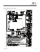
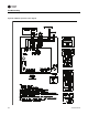
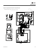
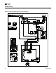
• Check wiring to make sure speed control is wired correctly. See Figure 63, p. 111 to Figure 64,
p. 112 for wiring schematic.
• Check voltage selection switch on side of Variable speed motor control.
• Should be set for motor voltage.
• To check speed control
• Turn voltage selection switch fully CCW
• Turn Motor speed control potentiometer fully CCW
• Motor should remain off
• Turn voltage selection switch fully CW
• Motor speed control potentiometer still fully CCW
• Measure motor voltage. Should be no more than 8VAC lower than line voltage
• With voltage selection switch still fully CW
• Turn Motor speed control potentiometer slowly fully CW (HI)
• Should go to full speed smoothly
If it fails any of these tests replace PSC motor speed controller.
Testing ECM-DCU and ECM-VCU Fan Control
WARNING
Live Electrical Components!
During installation, testing, servicing and troubleshooting of this product, it may be necessary
to work with live electrical components. Have a qualified licensed electrician or other individual
who has been properly trained in handling live electrical components perform these tasks.
Failure to follow all electrical safety precautions when exposed to live electrical components
could result in death or serious injury.
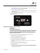
If ECM is not controlling Fan Motor properly inspect the following:
Note: The ECM controller has 4 wire pin connector that has an enable binary output and a
Variable speed analog output.
1. Incorrect supply voltage/No voltage
• Measure the power input to 24VAC terminal and Common/ground terminal of the ECM
board. The supply voltage should be between 19.2 and 28.2 VAC (24VAC cataloged).
However, voltages at either extreme may result in system instability.
• If low or no voltage, check up stream of controller to see how voltage has been interrupted.
See complete wiring diagrams (Figure 59, p. 107 to Figure 66, p. 114).
2. Testing Binary Output on ECM Board
• Measure Voltage from White to Green wire on connector
• Should be between 9 to 30VDC. If not replace ECM
3. Testing Analog variable speed output
• On ECM-DCU change board selector switches to 0 on each one of the switches to give you
a 100% output signal. On ECM-VCU adjust potentiometer until Led's read a 100% output.
• Measure voltage from green to red wires on 4 pin connector and document. See Figure 65,
p. 113 to Figure 66, p. 114 for correct unit wiring diagram.
• Should measure above 9VDC
• Change ECM-DCU board selector switches to 9 on tens digit and 9 on units digit to give you
a 99% output signal. On ECM-VCU adjust potentiometer until Led's read a 99% output.