
Programming Guide

VAV-SVP01A-EN 83
Troubleshooting
WARNING
Live Electrical Components!
During installation, testing, servicing and troubleshooting of this product, it may be necessary
to work with live electrical components. Have a qualified licensed electrician or other individual
who has been properly trained in handling live electrical components perform these tasks.
Failure to follow all electrical safety precautions when exposed to live electrical components
could result in death or serious injury.
Chapter Overview
This chapter contains information about the following:
• Diagnosing the Problem
• Diagnostic Log
• Diagnostic Table
• LED Operation
• Troubleshooting Procedures
• VV550 Failure Procedures
• VV550 Communication Loss Procedures
• Wired Zone Sensor Failure Procedures
• Wired Zone Setpoint Failure Procedures
• Wireless Zone Sensor Failure Procedures
• Airflow Failure Procedures
• Duct Temperature Sensor Failure Procedures
• VAV Damper Failure Procedures
• VAV Series Fan Failure Procedures
• VAV Parallel Fan Failure Procedures
• VAV Electric Heat Stage(s) Failure Procedures
• VAV Proportional Hot Water Failure Procedures
• Trane/Honeywell Proportional Valve Check Out Procedure
• VAV Two Position Hot Water Failure Procedures
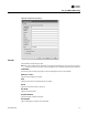
Diagnosing the Problem
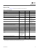
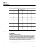
Green Status LED will give you an indication if a diagnostic is present. If diagnostic is present, use
Rover Service tool or Tracer Summit to access VV550 diagnostics. See Table 16, p. 85 for
diagnostics. After diagnostics have been assessed, find correct procedures for troubleshooting
issue.
Note: VV550 binary outputs can be exercised by Rover Service tool. See status and programming
sections for detail