Split System Cooling Units Split System Cooling Units TTA075A-TTA200B Air Handlers TWE050A-TWE200B 50 Hz December 2000 SS-PRC003-EN
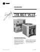
Introduction Split System Heat Pump Units… Designed With Your Needs In Mind. The Trane reputation for quality and reliability in air conditioning continues with the Odyssey™ family of light commercial split systems. Trane paid attention to your needs to make sure you get a system that will meet your job requirements every time...and at a competitive price. ©American Standard Inc.
Contents Introduction Features and Benefits 2 Application Considerations 7 Selection Procedure 8 4 Model Number Description General Data 9 10 Performance Data 13 Cooling Performance Fan Performance SS-PRC003-EN Electric Power 13 39 46 Connection and Wiring 48 Dimension and Weights 54 Mechanical Specifications 75 3
Features and Benefits Condensing Units • Trane 3-D® scroll compressor (TTA075-100A) • (2)Trane Climatuff compressors ™ (TTA100-125B) with independent refrigerant circuits • (2)Trane 3-D scroll compressors (TTA155-200B) with independent refrigerant circuits • 2) Manifolded scroll compressors with unloading capability (TTA100-155C) • Compressor motor overload protection • Control transformer • High and low pressure cutout switches • Internal pressure relief valve (TTA100B125B) • Liquid line filter drier, f
Features and Benefits Condensing Units Options The Odyssey™ split system product line includes condensing units in both single unloading and dual compressor options. TTA075A andTTA100A-ton single compressor models feature single refrigeration circuitry lowering job installation costs by requiring only one set of refrigerant lines.These units are ideal for their low cost, new construction jobs, as well as renovation and replacement buildings.
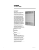
Features and Benefits Air Handlers Offer More Flexibility Flexibility is a key to meeting changing market requirements. Odyssey split systems offer not only various compressor options but also convertible air handlers.The air handlers can be installed either vertically in a mechanical room or horizontally above a ceiling. They do not require any removal of panels or reconfiguration of the drain pan to make either airflow application work.
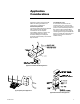
Application Considerations Application of this product should be within the catalogued airflow and performance considerations. Clearance Requirements The recommended clearances identified with unit dimensions should be maintained to assure adequate serviceability, maximum capacity and peak operating efficiency. Actual clearances that appear inadequate should be reviewed with your localTrane Representative. Low Ambient Cooling As manufactured, these units can operate to 35°F (1.
Selection Procedure Cooling Capacity Step 1 — Calculate the building’s total and sensible cooling loads at design conditions. Use theTrane calculation form or any other standard accepted method. Note:The formula below the table can be used to calculate Fan Motor Heat, 3.5 x Bhp = MBh 3.5 x 1.17 = 4.10 MBh Step 2 — Size the equipment usingTable 13-1. Match the cooling loads at design conditions. NetTotal Cooling Capacity = 77.7 MBh – 4.10 = 73.6 MBh 16.8 - 1.2 = 15.6 kW Net Sensible Cooling Capacity = 57.
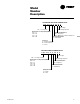
Model Number Description CONDENSING UNIT MODEL NOMENCLATURE T T A 0 7 5 A D 0 0 B 0 Service Digit TTA = Cooling Only Nominal Gross Cooling Capacity (MBh) 075 = 75 100 = 100 155 = 155 200 = 200 Minor Design Sequence Factory Installed Options 00 = No Options 0S = Black Epoxy Coated Condenser Coil Electrical Characteristics D = 380-415/3/50 Compressor A = Single Compressor B = Dual Compressor C = Scroll AIR HANDLER MODEL NOMENCLATURE T W E 0 5 0 A D 0 0 B 0 Service Digit TWE = Cooling Convertible Minor Desi
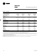
General Data Condensing Unit Table GD-1 — General Data Cooling Performance1 Gross Cooling Capacity, btu (kW) Matched Air Handler (kW) Condensing Unit Only2 (kW) ARI Net Cooling Capacity3 (kW) System Power kW Condensing Unit Power kW Compressor Number Type No. Speeds No. Motors Motor HP (kW) Motor RPM ARI Sound Rating (Bels)4 System Data5 No. Refrigerant Circuits Suction Line in. (mm) OD Liquid Line in. (mm) OD Outdoor Coil — Type Tube Size in. (mm) OD Face Area, sq.
General Data Condensing Unit Table GD-2— General Data Cooling Performance1 Gross Cooling Capacity, btu (kW) Matched Air Handler Condensing Unit Only2 ARI Net Cooling Capacity3 System Power kW Condensing Unit Power kW Compressor Number Type No. Speeds No. Motors Motor HP (kW) Motor RPM ARI Sound Rating (Bels)4 System Data5 No. Refrigerant Circuits Suction Line in. (mm) OD Liquid Line in. (mm) OD Outdoor Coil — Type Tube Size in. (mm) OD Face Area, sq. ft (m2) Rows Fins Per Inch Outdoor Fan Type No.
General Data Air Handler Table GD-3 — General Data TWE050A System Data1 No. Refrigerant Circuits 1 Suction Line in. (mm) OD 1.120(28.4) Liquid Line in. (mm) OD 0.38(9.7) Indoor Coil — Type Plate Fin Tube Size in. (mm) OD 0.375(9.5) 5.00(.47) Face Area sq. ft (m2) Rows 3 Fins Per Inch 12 Refrigerant Control Expansion Valve Drain Connection No. 4 Drain Connection Size in. (mm) 0.75(19.0) Drain Connection Type PVC Indoor Fan Type FC Centrifugal No. Used 1 Diameter in. (mm) 12.0(304.8) Width in. (mm) 12.
Performance Data System Table PD-1 — Gross Cooling Capacities (MBh) TTA075A Condensing Unit with TWE075A Air Handler (I-P) Ambient Temperature (°F) 85 CFM Airflow 2250 2500 2750 3000 Enter. Dry Bulb (°F) 75 80 85 90 75 80 85 90 75 80 85 90 75 80 85 90 61 TGC 75.7 76.2 77.8 81.8 77.3 77.9 80.4 84.6 78.6 79.4 82.7 86.9 79.7 80.8 84.6 89.0 SHC 59.6 69.5 77.8 81.8 62.3 73.2 80.4 84.6 64.9 76.7 82.7 86.9 67.3 80.1 84.6 89.0 67 TGC 83.5 83.7 84.1 84.6 85.1 85.3 85.7 86.4 86.3 86.6 87.0 88.0 87.4 87.
Performance Data System Table PD-2 — Gross Cooling Capacities (MBh) TTA075A Condensing Unit with TWE100A Air Handler (I-P) Ambient Temperature (°F) 85 CFM Airflow 2550 2875 3200 3525 Enter. Dry Bulb (°F) 75 80 85 90 75 80 85 90 75 80 85 90 75 80 85 90 61 TGC 79.9 80.7 83.7 88.0 81.5 82.8 86.7 91.2 82.9 84.6 89.2 93.9 84.2 86.6 91.4 96.2 SHC 65.5 77.2 83.7 88.0 69.1 82.3 86.7 91.2 72.6 84.6 89.2 93.9 75.9 86.6 91.4 96.2 67 TGC 87.9 88.1 88.5 89.5 89.5 89.8 90.3 91.2 90.8 91.2 91.9 93.9 91.6 92.
Performance Data System Table PD-3 — Gross Cooling Capacities (MBh) TTA085A Condensing Unit with TWE075A Air Handler (I-P) Ambient Temperature (°F) 85 CFM Airflow 2250 2500 2750 3000 Enter. Dry Bulb (°F) 75 80 85 90 75 80 85 90 75 80 85 90 75 80 85 90 61 TGC 83.0 83.2 83.7 86.2 84.8 85.2 86.1 89.5 86.6 87.0 88.3 92.4 88.1 88.5 90.2 95.0 SHC 61.8 70.5 79.6 86.2 64.2 73.9 84.0 89.5 66.6 77.1 88.1 92.4 68.9 80.2 90.2 95.0 67 TGC 92.0 92.3 92.4 92.8 94.2 94.5 94.6 95.0 96.0 96.3 96.5 96.9 97.5 97.
Performance Data System Table PD-4 — Gross Cooling Capacities (MBh) TTA085A Condensing Unit with TWE100A Air Handler (I-P) Ambient Temperature (°F) 85 CFM Airflow 2500 2800 3100 3400 Enter. Dry Bulb (°F) 75 80 85 90 75 80 85 90 75 80 85 90 75 80 85 90 61 67 95 73 TGC SHC TGC SHC TGC SHC 87.9 67.0 97.4 57.4 107.7 39.8 88.3 77.4 97.8 65.0 107.9 51.3 89.3 88.1 98.0 75.3 108.3 62.2 93.2 93.2 98.3 85.7 108.7 73.0 90.0 70.2 99.6 56.2 109.9 40.6 90.5 81.6 100.1 68.1 110.2 53.1 92.0 92.0 100.3 79.
Performance Data System Table PD-5 — Gross Cooling Capacities (MBh) TTA100A Condensing Unit with TWE100A Air Handler (I-P) Ambient Temperature (°F) 85 CFM Airflow 3025 3350 3675 4000 Enter. Dry Bulb (°F) 75 80 85 90 75 80 85 90 75 80 85 90 75 80 85 90 61 TGC 102.0 102.4 103.6 107.8 104.1 104.6 106.1 111.5 106.0 106.6 109.1 114.7 107.6 108.4 111.8 117.6 SHC 77.6 89.6 101.9 107.8 80.8 93.8 106.1 111.5 83.8 97.8 109.1 114.7 86.7 101.7 111.8 117.6 67 TGC 112.8 113.2 113.4 113.8 115.1 115.5 115.
Performance Data System Table PD-6 — Gross Cooling Capacities (MBh) TTA100B Condensing Unit with TWE100B Air Handler (I-P) Ambient Temperature (°F) 85 CFM Airflow 3000 3325 3675 4000 Enter. Dry Bulb (°F) 75 80 85 90 75 80 85 90 75 80 85 90 75 80 85 90 61 TGC 94.9 95.1 97.0 102.0 96.7 97.3 100.1 105.4 98.5 99.3 103.1 108.5 99.9 101.1 105.6 111.2 SHC 74.4 86.5 97.0 102.0 77.6 90.9 100.1 105.4 81.0 95.4 103.1 108.5 83.9 99.4 105.6 111.2 67 TGC 105.3 105.5 105.6 105.9 107.3 107.5 107.6 108.2 109.
Performance Data System Table PD-7 — Gross Cooling Capacities (MBh) - Both Compressors - TTA100C Condensing Unit with TWE100A Air Handler (I-P) Ambient Temperature (°F) 85 CFM Airflow 3000 3325 3650 4000 Enter. Dry Bulb (°F) 75 80 85 90 75 80 85 90 75 80 85 90 75 80 85 90 61 TGC 99.7 100.2 102.1 107.3 101.7 102.4 105.4 110.9 103.6 104.5 108.6 114.2 105.0 106.3 111.2 116.9 SHC 78.1 90.9 102.1 107.3 81.6 95.6 105.4 110.9 85.1 100.4 108.6 114.2 88.3 104.8 111.2 116.9 67 TGC 110.4 110.7 110.9 111.
Performance Data System Table PD-8 — Gross Cooling Capacities (MBh) - Single Compressor - TTA100C Condensing Unit with TWE100A Air Handler (I-P) Ambient Temperature (°F) 85 CFM Airflow 3000 3325 3650 4000 Enter. Dry Bulb (°F) 75 80 85 90 75 80 85 90 75 80 85 90 75 80 85 90 61 TGC 62.7 65.8 69.8 73.7 63.7 67.4 71.5 75.6 64.8 68.9 73.0 77.2 65.8 70.1 74.3 78.6 SHC 60.3 65.8 69.8 73.7 63.5 67.4 71.5 75.6 64.8 68.9 73.0 77.2 65.8 70.1 74.3 78.6 67 TGC 68.8 69.1 69.8 73.8 69.6 69.9 71.5 75.6 70.3 70.
Performance Data System Table PD-9 — Gross Cooling Capacities (MBh) TTA125B Condensing Unit with TWE100B Air Handler (I-P) Ambient Temperature (°F) 85 CFM Airflow 3000 3325 3675 4000 Enter. Dry Bulb (°F) 75 80 85 90 75 80 85 90 75 80 85 90 75 80 85 90 61 TGC 108.2 108.2 108.2 110.2 110.0 110.0 110.1 115.3 111.8 111.8 115.4 120.8 113.5 113.5 120.2 123.1 SHC 79.4 93.1 105.3 110.2 83.1 97.4 110.1 115.3 87.0 102.0 115.4 120.8 90.7 106.2 120.2 123.1 67 TGC 117.8 117.8 117.8 117.8 119.6 119.6 119.
Performance Data System Table PD-10 — Gross Cooling Capacities (MBh) TTA125B Condensing Unit with TWE155B Air Handler (I-P) Ambient Temperature (°F) 85 CFM Enter. Dry Bulb 61 67 95 73 61 67 105 Entering Wet Bulb (°F) 73 61 67 115 73 61 67 Airflow (°F) TGC SHC TGC SHC TGC SHC TGC SHC TGC SHC TGC SHC TGC SHC TGC SHC TGC SHC TGC SHC TGC SHC 75 120.8 96.6 132.7 73.8 141.1 49.7 113.8 93.7 124.9 70.8 132.7 46.7 106.3 90.5 116.6 67.6 123.9 43.6 98.8 87.4 108.3 64.6 80 120.8 114.3 132.7 91.
Performance Data System Table PD-11 — Gross Cooling Capacities (MBh) TTA155B Condensing Unit with TWE155B Air Handler (I-P) Ambient Temperature (°F) 85 CFM Airflow 4500 5000 5500 6000 Enter. Dry Bulb (°F) 75 80 85 90 75 80 85 90 75 80 85 90 75 80 85 90 61 TGC 153.6 154.5 157.8 165.9 156.7 158.0 163.0 171.5 159.4 161.0 167.6 176.3 161.6 163.8 171.7 180.7 SHC 120.6 140.6 157.8 165.9 126.1 148.1 163.0 171.5 131.3 155.3 167.6 176.3 136.3 162.2 171.7 180.7 67 TGC 169.3 169.7 170.7 171.6 172.4 172.
Performance Data System Table PD-12— Gross Cooling Capacities (MBh) TTA155B Condensing Unit with TWE200B Air Handler (I-P) Ambient Temperature (°F) 85 CFM Airflow 4500 5000 5500 6000 Enter. Dry Bulb (°F) 75 80 85 90 75 80 85 90 75 80 85 90 75 80 85 90 61 TGC 158.1 159.2 163.2 171.5 161.4 162.8 168.7 177.4 164.1 166.0 173.5 182.5 166.3 168.5 177.7 187.1 SHC 125.3 146.5 163.2 171.5 131.2 154.7 168.7 177.4 136.9 162.5 173.5 182.5 142.4 168.5 177.7 187.1 67 TGC 174.1 174.5 175.5 176.6 177.3 177.
Performance Data System Table PD-13 — Gross Cooling Capacities (MBh) - Both Compressors - TTA155C Condensing Unit With TWE155B Air Handler (I-P) Ambient Temperature (°F) 85 CFM Airflow 4500 5000 5500 6000 Enter. Dry Bulb (°F) 75 80 85 90 75 80 85 90 75 80 85 90 75 80 85 90 61 TGC 147.1 147.9 152.6 160.5 150.0 151.2 157.6 165.9 152.4 154.3 162.0 170.7 154.4 157.1 165.9 174.9 SHC 118.2 138.6 152.6 160.5 123.9 146.4 157.6 165.9 129.4 153.9 162.0 170.7 134.6 157.1 165.9 174.9 67 TGC 163.0 163.3 163.
Performance Data System Table PD-14 — Gross Cooling Capacities (MBh) - Single Compressor - TTA155C Condensing Unit with TWE155B Air Handler (I-P) Ambient Temperature (°F) 85 CFM Airflow 4500 5000 5500 6000 Enter. Dry Bulb (°F) 75 80 85 90 75 80 85 90 75 80 85 90 75 80 85 90 61 TGC 90.4 96.3 102.2 108.3 92.5 98.6 104.7 111.0 94.4 100.6 106.9 113.2 96.0 102.3 108.7 115.1 SHC 90.4 96.3 102.2 108.3 92.5 98.6 104.7 111.0 94.4 100.6 106.9 113.2 96.0 102.3 108.7 115.1 67 TGC 99.1 99.6 102.3 108.4 100.
Performance Data System Table PD-15 — Gross Cooling Capacities (MBh) TTA200B Condensing Unit with TWE200B Air Handler (I-P) Ambient Temperature (°F) 85 CFM Airflow 6000 6675 7350 8025 Enter. Dry Bulb (°F) 75 80 85 90 75 80 85 90 75 80 85 90 75 80 85 90 61 TGC 201.0 202.2 206.7 217.1 204.9 206.6 213.4 224.4 208.3 210.6 219.4 230.7 211.2 214.3 224.6 236.3 SHC 158.5 184.9 206.7 217.1 165.7 194.8 213.4 224.4 172.6 204.3 219.4 230.7 179.2 213.5 224.6 236.3 67 TGC 221.1 221.6 222.8 224.1 225.2 225.
Performance Data Condensing Unit Table PD-16 — Cooling Performance (MBh) TTA075A Condensing Unit Only ODTemp (I-P) Suction Reference Temperature °F °F 30 35 40 45 50 55 65 Head press psig Cap. Btu/1000 OD Unit kW 175 69.1 5.01 181 76.2 5.13 188 83.6 5.27 195 91.2 5.40 202 99.0 5.55 210 106.9 5.70 75 Head press psig Cap. Btu/1000 OD Unit KW 202 66.9 5.54 209 73.7 5.68 216 80.7 5.82 223 87.9 5.97 231 95.3 6.12 239 102.8 6.28 85 Head press psig Cap. Btu/1000 OD Unit KW 232 64.1 6.
Performance Data Condensing Unit Table PD-17 — Cooling Performance (MBh) TTA085A Condensing Unit Only OD Temp (I-P) Suction Reference Temperature °F °F 30 35 40 45 50 55 65 Head press PSIG Cap. Btuh/1000 OD Unit KW 160 79.8 5.64 164 88.0 5.73 169 96.6 5.83 173 105.7 5.93 178 115.1 6.04 184 124.9 6.15 75 Head press PSIG Cap. Btuh/1000 OD Unit KW 185 76.4 6.14 189 84.1 6.23 194 92.3 6.33 199 100.8 6.44 204 109.8 6.56 209 119.2 6.68 85 Head press PSIG Cap.
Performance Data Condensing Unit Table PD-18 — Cooling Performance (MBh) TTA100A Condensing Unit Only ODTemp (I-P) Suction Reference Temperature °F °F 30 35 40 45 50 55 65 Head press PSIG Cap. Btuh/1000 OD Unit KW 174 95.7 6.69 180 105.0 6.84 186 114.7 7.01 193 124.8 7.19 199 135.3 7.37 207 146.1 7.58 75 Head press PSIG Cap. Btuh/1000 OD Unit KW 200 91.2 7.38 206 99.9 7.54 212 109.1 7.72 219 118.7 7.91 226 128.8 8.12 234 139.2 8.34 85 Head press PSIG Cap.
Performance Data Condensing Unit Table PD-19 — Cooling Performance (MBh) TTA100B Condensing Unit Only OD Temp (I-P) Suction Reference Temperature °F °F 30 35 40 45 50 55 65 Head press PSIG Cap. Btuh/1000 OD Unit KW 172 93.8 7.46 178 103.2 7.69 184 113.0 7.90 191 123.2 8.11 198 133.8 8.32 205 144.7 8.52 75 Head press PSIG Cap. Btuh/1000 OD Unit KW 197 88.4 8.00 203 97.4 8.27 210 106.7 8.54 217 116.4 8.79 224 126.5 9.05 232 136.9 9.31 85 Head press PSIG Cap.
Performance Data Condensing Unit Table PD-20 — Gross Cooling Capacities (MBh) - Both Compressors - (I-P) TTA100C Condensing Unit Only ODTemp Suction Reference Temperature °F °F 30 35 40 45 50 55 65 Head press PSIG Cap. Btuh/1000 OD Unit KW 147.0 95.6 5.6 152.8 105.6 5.8 158.9 116.2 5.9 165.3 127.2 6.1 172.1 138.7 6.3 179.4 150.7 6.4 75 Head press PSIG Cap. Btuh/1000 OD Unit KW 169.9 90.8 6.2 175.8 100.4 6.3 182.2 110.4 6.5 188.9 121.0 6.7 196.0 132.1 6.8 203.6 143.6 7.
Performance Data Condensing Unit Table PD-21 — Gross Cooling Capacities (MBh) - Single Compressor - (I-P) TTA100C Condensing Unit Only OD Temp Suction Reference Temperature °F °F 30 35 40 45 50 55 65 Head press PSIG Cap. Btuh/1000 OD Unit KW 119.4 52.0 2.9 122.4 58.0 3.0 125.5 64.3 3.1 128.8 70.8 3.1 132.2 77.6 3.2 135.8 84.7 3.2 75 Head press PSIG Cap. Btuh/1000 OD Unit KW 140.4 49.6 3.2 143.6 55.3 3.2 146.8 61.3 3.3 150.3 67.6 3.3 153.9 74.1 3.4 157.6 80.9 3.
Performance Data Condensing Unit Table PD-22 — Cooling Performance (MBh) TTA125B Condensing Unit Only ODTemp (I-P) Suction Reference Temperature °F °F 30 35 40 45 50 55 65 Head press PSIG Cap. Btuh/1000 OD Unit KW 169 115.6 8.89 174 127.1 9.17 180 139.1 9.43 186 151.6 9.70 193 164.5 9.96 199 177.9 10.23 75 Head press PSIG Cap. Btuh/1000 OD Unit KW 194 109.1 9.43 200 120.1 9.77 206 131.6 10.10 212 143.5 10.43 219 155.9 10.76 227 168.6 11.10 85 Head press PSIG Cap.
Performance Data Condensing Unit Table PD-23 — Cooling Performance (MBh) TTA155B Condensing Unit Only OD Temp (I-P) Suction Reference Temperature °F °F 30 35 40 45 50 55 65 Head press PSIG Cap. Btuh/1000 OD Unit KW 173 140.3 9.95 179 154.9 10.20 186 170.1 10.48 194 185.9 10.78 201 202.2 11.10 209 218.8 11.43 75 Head press PSIG Cap. Btuh/1000 OD Unit KW 200 136.0 11.00 206 150.0 11.28 214 164.4 11.58 221 179.3 11.90 229 194.6 12.23 238 210.3 12.58 85 Head press PSIG Cap.
Performance Data Condensing Unit Table PD-24 — Gross Cooling Capacities (MBh) - Both Compressors - (I-P) TTA155C Condensing Unit Only OD Temp Suction Reference Temperature °F °F 30 35 40 45 50 55 65 Head press. PSIG Cap. Btuh/1000 OD Unit KW 164.9 132.3 9.3 170.4 146.2 9.5 176.3 160.9 9.7 182.6 176.2 10.0 189.2 192.1 10.2 196.0 208.5 10.5 75 Head press. PSIG Cap. Btuh/1000 OD Unit KW 191.3 128.5 10.3 197.3 142.0 10.5 203.6 156.0 10.7 210.3 170.6 11.0 217.2 185.6 11.3 224.4 201.
Performance Data Condensing Unit Table PD-25 — Cooling Performance (MBh) - Single Compressor - (I-P) TTA155C Condensing Unit Only ODTemp Suction Reference Temperature °F °F 30 35 40 45 50 55 65 Head press. PSIG Cap. Btuh/1000 OD Unit KW 137.1 67.8 4.8 139.8 75.1 4.8 142.6 82.9 4.8 145.7 91.3 4.9 149.0 100.1 5.0 152.4 109.4 5.0 75 Head press. PSIG Cap. Btuh/1000 OD Unit KW 161.2 66.9 5.1 164.2 74.1 5.2 167.3 81.7 5.3 170.6 89.7 5.3 174.1 98.1 5.4 177.7 106.9 5.5 85 Head press.
Performance Data Condensing Unit Table PD-26 — Cooling Capacities (MBh) TTA200B Condensing Unit Only ODTemp (I-P) Suction Reference Temperature °F °F 30 35 40 45 50 55 65 Head press PSIG Cap. Btuh/1000 OD Unit KW 181 188.3 12.97 187 206.3 13.31 194 225.0 13.66 201 244.3 14.04 208 264.3 14.45 216 285.0 14.88 75 Head press PSIG Cap. Btuh/1000 OD Unit KW 207 179.3 14.39 214 196.2 14.76 221 213.9 15.15 229 232.4 15.57 237 251.6 16.02 245 271.4 16.48 85 Head press PSIG Cap.
Performance Data Air Handler Table PD-27— Evaporator Fan Performance — TWE050A (I-P) External Static Pressure (Inches of Water Column) CFM .10" .20" .30" .40" .50" .60" .70" .80" .90" 1.00" 1.10" RPM BHP RPM BHP RPM BHP RPM BHP RPM BHP RPM BHP RPM BHP RPM BHP RPM BHP RPM BHP RPM BHP 1400 1500 1600 1700 1800 1900 2000 2100 — — — 601 625 642 659 674 — — — 646 0.37 698 — 607 0.36 661 0.40 713 — 625 0.38 676 0.43 727 0.35 648 0.40 696 0.44 744 0.36 671 0.41 716 0.46 762 0.40 687 0.45 731 0.50 776 0.
Performance Data Air Handler Table PD-29— Evaporator Fan Performance TWE075A (I-P) External Static Pressure (In. Of Water Column) 0.10 0.20 0.30 0.40 0.50 0.60 0.70 0.80 0.90 1.00 1.10 RPM BHP RPM BHP RPM BHP RPM BHP RPM BHP RPM BHP RPM BHP RPM BHP RPM BHP RPM BHP RPM BHP CFM 2000 2125 2250 2375 2500 2625 2750 2875 3000 — — 443 0.44 489 — — 453 0.46 499 — — 463 0.49 510 — — 473 0.51 520 445 0.47 489 0.54 533 464 0.50 506 0.57 548 484 0.53 523 0.59 562 504 0.56 540 0.62 576 524 0.59 557 0.65 590 1.
Performance Data Air Handler Table PD-31 — Evaporator Fan Performance TWE100A,TWE100B (I-P) External Static Pressure (In. Of Water Column) CFM 0.10 0.20 0.30 0.40 0.50 0.60 0.70 0.80 0.90 1.00 1.20 RPM BHP RPM BHP RPM BHP RPM BHP RPM BHP RPM BHP RPM BHP RPM BHP RPM BHP RPM BHP RPM BHP 1.5 HP Standard Motor and Low Static Drive 2600 460 0.32 493 0.39 527 0.47 565 0.55 603 0.63 641 0.71 2775 473 0.37 506 0.45 540 0.53 576 0.61 613 0.69 649 0.77 2950 487 0.43 519 0.50 552 0.58 587 0.67 623 0.75 658 0.
Performance Data Air Handler Table PD-33 — Evaporator Fan Performance — TWE155B (I-P) External Static Pressure (Inches of Water Column) CFM 4000 4250 4500 4750 5000 5260 5500 5750 6000 .10" .20" .30" .40" .50" .60" .70" .80" .90" 1.00" 1.20" 1.40" RPM BHP RPM BHP RPM BHP RPM BHP RPM BHP RPM BHP RPM BHP RPM BHP RPM BHP RPM BHP RPM BHP RPM BHP 628 633 637 641 645 650 652 653 655 1.34 1.37 1.40 1.42 1.44 1.46 1.47 1.48 1.49 653 658 662 666 670 675 678 680 681 1.38 1.41 1.44 1.50 1.52 1.53 1.55 1.57 1.
Performance Data Air Handler Table PD-35 — Evaporator Fan Performance TWE200B (I-P) External Static Pressure (In. Of Water Column) CFM 0.10 0.20 0.30 0.40 0.50 0.60 0.70 0.80 0.90 1.00 1.20 140 RPM BHP RPM BHP RPM BHP RPM BHP RPM BHP RPM BHP RPM BHP RPM BHP RPM BHP RPM BHP RPM BHP RPM BHP 5200 — — 5525 — — 5850 — — 6175 473 0.99 6500 492 1.12 6825 510 1.25 7150 528 1.38 7475 550 1.61 7800 572 1.83 3.0 HP Standard Motor and Low Static Drive 461 0.74 503 0.91 545 479 0.88 521 1.04 563 497 1.01 539 1.
Performance Data Table PD-37— Discharge Plenum And Grille Assembly Throw Distance (ft) — Air Handler Unit Model No. m3/h 2380 2718 3060 3398 3737 3568 4079 4586 5098 5436 6116 6797 7477 8154 7304 8327 9176 10195 9515 10872 12233 13594 CFM 1400 1600 1800 2000 2200 2100 2400 2700 3000 3200 3600 4000 4400 4800 4300 4900 5400 6000 5600 6400 7200 8000 TWE050 TWE075 TWE100 TWE155 TWE200 Straight 38 (11.6) 42 (12.8) 46 (14.0) 48 (14.6) 51 (15.5) 49 (14.9) 52 (15.9) 55 (16.8) 58 (17.7) 56 (17.1) 62 (18.
Performance Data Table PD-39 — Auxiliary Electric Heat Capacity — Air Handler Unit Model No. TWE050/075/100AD TWE100BD TWE075, 100AD TWE100BD TWE155,200B Total kW 5.00 9.96 14.96 24.92 No. of Stages 1 1 1 2 34.88 10.00 19.92 29.92 49.84 2 1 1 2 2 Stage 1 kW Btu Input Output 5.00 17,065 9.96 33,993 14.96 51,058 14.96 51,058 Stage 2 kW Btu Input Output — — — — — — 9.96 33,993 kW Input 5.00 9.96 14.96 24.92 Btu Output 17,065 33,993 51,058 85,051 19.92 10.00 19.92 19.92 29.92 14.96 — — 10.00 19.
Electrical Data Table ED-1 — Unit Wiring — Condensing Units Unit Model No. Unit Operating Voltage Minimum Circuit Ampacity Maximum Fuse Size or Maximum Circuit Breaker TTA075A TTA085A TTA100A TTA100B TTA125B TTA155B TTA155C TTA200B 380/415 380/415 380/415 380/415 380/415 380/415 380/415 380/415 15.5 17.8 21.5 26.3 27.4 28.3 35.1 39.3 25 25 35 35 35 35 45 50 Table ED-2 — Electrical Characteristics — Motors — Condensing Units Compressor Motor Condenser Fan Motor Amps Unit Model No.
Electric Heat Data Table ED-5 — Unit Wiring With Electric Heat (Single Point Connection) — Air Handlers Heater Model No. BAYHTRL405A BAYHTRL410A BAYHTRL415A BAYHTRL425A BAYHTRL405A BAYHTRL410A BAYHTRL415A BAYHTRL425A BAYHTRL435A BAYHTRL405A BAYHTRL410A BAYHTRL415A BAYHTRL425A BAYHTRL435A BAYHTRM410A BAYHTRM420A BAYHTRM430A BAYHTRM450A BAYHTRM410A BAYHTRM420A BAYHTRM430A BAYHTRM450A Heater kW Rating1 5.00 9.96 14.96 24.92 5.00 9.96 14.96 24.92 34.88 5.00 9.96 14.96 29.92 34.88 10.00 19.92 29.92 49.84 10.
Jobsite Connections Wiring shown with dashed lines is to be furnished and installed by the customer. All customer- supplied wiring must be copper only and must conform to local electrical codes. NOTE: 1. When electric heater accessory is used, single point power entry or dual point power entry is field optional. Single point power entry option is through electric heater only. TTA050/TWE050A Field Wiring: A — 3 power wires. Line voltage for 3 phase, 2 wires for single phase. B — 3 power wires.
Typical Wiring Air Handler Air Handler Typical wiring diagram. For specific wiring, see individual Service Facts.
Typical Wiring Condensing Unit Condensing Unit — Single Compressor Typical wiring diagram. For specific wiring, see individual Service Facts.
Typical Wiring Condensing Unit Condensing Unit — Single Compressor SS-PRC003-EN 51
Typical Wiring Condensing Unit Condensing Unit — Dual Compressor Typical wiring diagram. For specific wiring, see individual Service Facts.
Typical Wiring Condensing Unit Condensing Unit — Dual Compressor C757164P01 SS-PRC003-EN 53
Dimensional Data Figure DD-1 — TTA075 Condensing Units All dimensions are in inches and millimeters. Note 1: Minimum Clearance for proper operation is 36 inches (914) from walls, shrubbery, privacy fences, etc. Minimum clearance between adjacent units is 72 inches (1829).
Dimensional Data Figure DD-2 — TTA085A and 100A Condensing Units All dimensions are in inches and millimeters. Note 1: Minimum Clearance for proper operation is 36 inches (914) from walls, shrubbery, privacy fences, etc. Minimum clearance between adjacent units is 72 inches (1829).
Dimensional Data Figure DD-3 — TTA100C Condensing Units All dimensions are in inches and millimeters. Note 1: Minimum Clearance for proper operation is 36 inches (914) from walls, shrubbery, privacy fences, etc. Minimum clearance between adjacent units is 72 inches (1829).
Dimensional Data Figure DD-4 — TTA100B and TTA125B Condensing Units All dimensions are in inches and millimeters.
Dimensional Data Figure DD- 5— TTA155B Condensing Unit All dimensions are in inches and millimeters. Note 1: Minimum Clearance for proper operation is 36 inches (914) from walls, shrubbery, privacy fences, etc. Minimum clearance between adjacent units is 72 inches (1829).
Dimensional Data Figure DD-6 — TTA155C Condensing Units All dimensions are in inches and millimeters. Note 1: Minimum Clearance for proper operation is 36 inches (914) from walls, shrubbery, privacy fences, etc. Minimum clearance between adjacent units is 72 inches (1829).
Dimensional Data Figure DD-7 — TTA200B Condensing Unit All dimensions are in inches and millimeters. Note 1: Minimum Clearance for proper operation is 36 inches (914) from walls, shrubbery, privacy fences, etc. Minimum clearance between adjacent units is 72 inches (1829).
Dimensional Data Figure DD-8 — TWE050A Air Handlers All dimensions are in inches and millimeters. Notes: 1. Length, Width, and Height Dimensions do not include 1/2” (12.7mm) access panel depth. 2. Removable drain pan and attached drain connection may be installed on either end of unit in either the vertical or horizontal configuration. Plastic drain pan access plate on the end of unit opposite drain connection must be removed to slide drain pan out for cleaning.
Dimensional Data Figure DD-9 — TWE075A Air Handlers All dimensions are in inches and millimeters. Notes: 1. Length, Width, and Height Dimensions do not include 1/2” (12.7mm) access panel depth. 2. Removable drain pan and attached drain connection may be installed on either end of unit in either the vertical or horizontal configuration. Plastic drain pan access plate on the end of unit opposite drain connection must be removed to slide drain pan out for cleaning.
Dimensional Data Figure DD-10 — TWE100A Air Handlers All dimensions are in inches and millimeters. Notes: 1. Length, Width, and Height Dimensions do not include 1/2” (12.7mm) access panel depth. 2. Removable drain pan and attached drain connection may be installed on either end of unit in either the vertical or horizontal configuration. Plastic drain pan access plate on the end of unit opposite drain connection must be removed to slide drain pan out for cleaning.
Dimensional Data Figure DD-11 — TWE100B Air Handlers All dimensions are in inches and millimeters. Notes: 1. Length, Width, and Height Dimensions do not include 1/2” (12.7mm) access panel depth. 2. Removable drain pan and attached drain connection may be installed on either end of unit in either the vertical or horizontal configuration. Plastic drain pan access plate on the end of unit opposite drain connection must be removed to slide drain pan out for cleaning.
Dimensional Data Figure DD-12 — TWE050A, 075A, 100A and TWE100B Air Handlers All dimensions are in inches and millimeters. Table DD-1 — Air Handler Dimensions — in. (mm) Model No. TWE050A TWE075A TWE100A TWE100B SS-PRC003-EN AA 35 5/8 (905) 45 1/8 (1146.2) 61 1/8 (1552.6) 61 1/8 (1552.6) AB 12 1/16 (306.4) 16 (406.4) 16 (406.4) 16 (406.4) AC 1 5/8 (41.3) 1 11/16 (42.9) 1 11/16 (42.9) 1 11/16 (42.9) AD 32 1/4 (819.2) 41 15/16 (1065.2) 57 15/16 (1471.6) 57 15/16 (1471.6) AE 2 15/16 (74.6) 6 5/8 (168.
Dimensional Data Figure DD-13 — TWE155B Air Handlers All dimensions are in inches and millimeters. Notes: 1. Length, Width, and Height Dimensions do not include 1/2” (12.7mm) access panel depth. 2. Removable drain pan and attached drain connection may be installed on either end of unit in either the vertical or horizontal configuration. Plastic drain pan access plate on the end of unit opposite drain connection must be removed to slide drain pan out for cleaning.
Dimensional Data Figure DD-14 — TWE200B Air Handlers All dimensions are in inches and millimeters. Notes: 1. Length, Width, and Height Dimensions do not include 1/2” (12.7mm) access panel depth. 2. Removable drain pan and attached drain connection may be installed on either end of unit in either the vertical or horizontal configuration. Plastic drain pan access plate on the end of unit opposite drain connection must be removed to slide drain pan out for cleaning.
Dimensional Data Figure DD-15 — TWE155B and 200B Air Handlers All dimensions are in inches and millimeters. Table DD-2 — Air Handler Dimensions — in. (mm) Model No. TWE155B TWE200B A 77 1/4 (1962.2) 89 1/4 (2267) B 1 3/16 (30.2) 1 11/16 (42.9) C 48 (1219.2) 50 13/16 (1290.6) D 11 7/16 (290.5) 11 1/2 (292.1) E 18 (457.2) 20 1/8 (511.2) F 3 3/8 (85.7) 3 1/16 (77.8) G 35 1/16 (890.6) 39 1/8 (993.8) H 73 7/8 (1876.4) 82 7/8 (2105) J 3 3/4 (95.3) 4 9/16 (115.9) P 2 7/8 (73) 4 /16 (122.
Dimensional Data Figure 16 — Electric Heater for TWE050, 075, 100 Air Handlers All dimensions are in inches and millimeters.
Dimensional Data Table DD-3 — Discharge Plenum And Grille Dimensions — in. (mm) Model TWE050 Model No. BAYPLNM015 TWE075 BAYPLNM016 TWE100 BAYPLNM017 Figure DD-18 — Discharge Plenum and Grille All dimensions are in inches and millimeters. A B C 3715/16 2115/16 28 (963.6) (557.2) (711.2) 471/2 25 28 (1206.5) (635) (711.2) 1 63 /2 25 28 (1612.9) (635) (711.2) Table DD-4 — Discharge Plenum And Grille Dimensions — in. (mm) For Use with Electric Heat Model TWE050 Model No.
Dimensional Data Figure DD-20 — Hot Water Coil All dimensions are in inches and millimeters. 3.00 (76 mm) DIA. HOLE FOR 2” (50.8 mm) NPT SUPPLY 3.00 (76 mm) DIA. HOLE FOR 2” (50.8 mm) NPT RETURN 329/32 99 mm BAYWATR017 3.00 (76 mm) DIA. HOLE FOR 2” (50.8 mm) NPT SUPPLY 3.00 (76 mm) DIA. HOLE FOR 2” (50.8 mm) NPT RETURN BAYWATR018 BAYWATR019 BAYWATR020 BAYWATR021 Table DD-6 — Hot Water Coil Dimensions — in. (mm) Model TWE050 Accessory No.
Dimensional Data Figure DD-21 — Steam Coil All dimensions are in inches and millimeters. Table DD-7 — Steam Coil Dimensions — in. (mm) Model TWE050 Accessory No. BAYWATR012 TWE075 BAYWATR013 TWE100 BAYWATR014 TWE155 BAYWATR015 TWE200 BAYWATR016 72 A 38 (965.2) 475/8 (1209.7) 635/8 (1616.1) 795/8 (2022.5) 925/8 (2352.7) B 221/8 (562) 253/16 (639.8) 253/16 (639.8) 2713/16 (706.4) 305/8 (777.9) C D E F 133/16 5 9 141/16 (335) (127) (228.6) (357.2) 1913/16 5 107/8 171/8 (503.2) (127) (276.
Weights Table W-1 — Unit and Corner Weights — lb (kg) Unit Model No. TTA075A TTA100A TTA100B TTA100C TTA125B TTA155B TTA155C TTA200B Shipping Maximum — lb (kg) 366 (166.0) 444 (201.4) 514 (233.1) 483 (219.1) 542 (245.9) 744 (337.5) 745 (337.9) 915 (415.0) Net Maximum — lb (kg) 322 (146.1) 390 (176.9) 460 (208.7) 428 (194.1) 488 (221.4) 668 (303.0) 660 (299.4) 830 (376.5) 1 105 (47.6) 134 (60.8) 153 (69.4) 139 (63.0) 153 (69.4) 192 (87.1) 216 (98.0) 240 (108.9) Corner Weights 2 3 80 59 (36.3) (26.8) 95.
Weights Table W-3 — Air Handlers, Coils, And Corner Weights — lb (kg)1 Unit Model No. TWE050 TWE075 TWE100 TWE125 TWE200 Shipping Maximum (lb) 298 (135) 388 (176) 473 (214.6) 754 (342) 886 (401.9) Net Maximum (lb) 262 (118.9) 346 (157) 419 (190.1) 690 (313) 820 (372) #1 59 (26.8) 79 (35.9) 107 (48.5) 173 (78.5) 204 (92.5) Corner Weights — Vertical #2 #3 59 59 (26.8) (26.8) 79 79 (35.9) (35.9) 107 107 (48.5) (48.5) 173 173 (78.5) (78.5) 204 204 (92.5) (92.5) #4 59 (26.8) 79 (35.9) 107 (48.5) 173 (78.
Mechanical Specifications General Units shall be assembled on heavy gauge steel mounting/lifting rails and shall be weatherproofed. Units shall include a hermetic scroll or reciprocating compressor(s), plate fin condenser coil, fans and motors, controls, and holding charge of nitrogen. Operating range shall be between 115°F (46.1°C) and 35°F (1.7°C) in cooling as standard from the factory. Units shall be rated in accordance with ARI Standard 210/240, 340/360 or 365.
Mechanical Specifications Controls Condensing units shall be completely factory wired with necessary controls and contactor pressure lugs or terminal block for power wiring. Control wiring shall be 24-volt control circuit which includes fusing and control transformer. Units shall provide external location for mounting a fused disconnect device.Time delay timers to prevent compressors in dual compressor units from simultaneous start-up and anti- recycle timers are available as optional accessories.
Mechanical Specifications General Air handler units shall be completely factory assembled including coil, condensate drain pan, fan motor(s), filters, and controls in an insulated casing that can be applied in either vertical or horizontal configuration. Units shall be rated and tested in accordance with ARI Standard 210, 240, 360. Casing Unit casing shall be constructed of zinc coated, heavy gauge, galvanized steel.
Literature Order Number TheTrane Company An American Standard Company www.trane.com For more information contact your local office or e-mail us at comfort@trane.com SS-PRC003-EN File No. PL-UN-SS-PRC003-EN-12-00 Supersedes SS-PRC003-EN 07-00 Stocking Location Inland - LaCrosse SinceTheTrane Company has a policy of continuous product and product data improvement, it reserves the right to change design and specifications without notice.