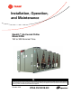
Installation, Operation, and Maintenance Stealth™ Air-Cooled Chiller Model RTAE 150 to 300 Nominal Tons SAFETY WARNING Only qualified personnel should install and service the equipment. The installation, starting up, and servicing of heating, ventilating, and airconditioning equipment can be hazardous and requires specific knowledge and training. Improperly installed, adjusted or altered equipment by an unqualified person could result in death or serious injury.
Warnings, Cautions and Notices Warnings, Cautions and Notices. Note that warnings, cautions and notices appear at appropriate intervals throughout this manual. Warnings are provided to alert installing contractors to potential hazards that could result in death or personal injury. Cautions are designed to alert personnel to hazardous situations that could result in personal injury, while notices indicate a situation that could result in equipment or property-damage-only accidents.
Warnings, Cautions and Notices WARNING Proper Field Wiring and Grounding Required! All field wiring MUST be performed by qualified personnel. Improperly installed and grounded field wiring poses FIRE and ELECTROCUTION hazards. To avoid these hazards, you MUST follow requirements for field wiring installation and grounding as described in NEC and your local/state electrical codes. Failure to follow code could result in death or serious injury.
Table of Contents Warnings, Cautions and Notices . . . . . . . . . . Factory Warranty Information . . . . . . . . . . . Copyright . . . . . . . . . . . . . . . . . . . . . . . . . . . . . Trademarks . . . . . . . . . . . . . . . . . . . . . . . . . . . Revision History . . . . . . . . . . . . . . . . . . . . . . . 2 Pressure Relief Valves . . . . . . . . . . . . . . . . . .26 3 3 Evaporator Waterside Pressure Drop Curves . . . . . . . . . . . . . . . . . . . . . . . . . . . . . . .
Compressor and Lube Oil System . . . . . . 40 Condenser and Fans . . . . . . . . . . . . . . . . . . 40 Running (Lag Compressor/Circuit Start and Run) . . . . . . . . . . . . . . . . . . . . . .63 Evaporator . . . . . . . . . . . . . . . . . . . . . . . . . . . 41 Satisfied Setpoint . . . . . . . . . . . . . . . . . . . .64 Drive Cooling System . . . . . . . . . . . . . . . . . 41 Normal Shutdown to Stopped or Run Inhibit . . . . . . . . . . . . . . . . . . . . . . . . .65 Controls . . . . . . . . . .
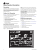
Model Number Description Nameplates of typical unit model number and the coding system for each. The Stealth™ outdoor unit nameplates are applied to the exterior of the Control Panel. A compressor nameplate is located on each compressor. When the unit arrives, compare all nameplate data with ordering, submittal, and shipping information. Each position, or group of positions, in the model number is used to represent a feature.
Model Number Descriptions Unit Model Number Digits 1,2 — Unit Model Digit 16 — Evaporator Application Digit 26 — Power Line Connection Type Digits 3— Unit Type F = A G = A C D C = RT = = Rotary Chiller Air-cooled Digits 4 — Development Sequence E = Development Sequence Digits 5-7 — Nominal Capacity 149 = 164 = 150 = 165 = 180 = 200 = 225 = 250 = 275 = 300 = 150 NominalTons Single Circuit 165 NominalTons Single Circuit 150 NominalTons 165 NominalTons 180 NominalTons 200 NominalTons 225 Nomi
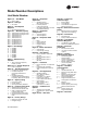
Model Number Descriptions Digit 34 — Structural Options A B = = C = D E F = = = Standard Unit Structure Seismic to International Building Code (IBC) California Office of Statewide Health Planning and Development (OSHPD) Certification Wind Load for Florida Hurricane 175 MPH Seismic (IBC) and Wind Load OSHPD and Wind Load Digit 35 — Appearance Options 0 A = = No Appearance Options Architectural Louvered Panels Digit 36 — Unit Isolation 0 1 3 = = = No Isolation Elastomeric Isolators Seismic Rated I
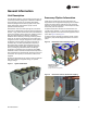
General Information Unit Description The 150-300 ton Stealth™ units are helical-rotary type, aircooled liquid chillers designed for installation outdoors. The compressor circuits are completely assembled, hermetic packages that are factory-piped, wired, leaktested, dehydrated, and tested for proper control operation before shipment. Chilled water inlet and outlet openings are covered for shipment.
General Data General Data Table 1. General data table Unit Size (tons) Compressor Model Quantity # 150 165 180 200 225 250 275 300 150SC 165SC CHHSR CHHSR CHHSR CHHSR CHHSS CHHSS CHHSS CHHSS CHHSS CHHSS 2 2 2 2 2 2 2 2 1 1 Evaporator Water Storage (gal) 17.5 18.7 21.9 23.9 26.6 28.7 33.0 36.0 17.3 17.3 (L) 66.1 70.9 82.8 90.5 100.6 108.8 125.0 136.1 65.6 65.6 (gpm) 171 187 202 228 261 288 318 354 169 169 (l/s) 10.8 11.8 12.7 14.4 16.
General Data Drive Cooling System Drive cooling fluid volumes are dependent on unit configuration. • • • Use Table 2 for units that meet the following criteria: Use Table 2 for units that meet the following criteria: • Model number digits 10, 11 = AC • Model number digits 10, 11 = AA • AND Digits 3-7 = 225, 250, 275 or 300 Use Table 2 for units that meet the following criteria: • AND Digit 22 = 1 or 2 • Model number digits 10, 11 = AB • AND Digits 28, 29 = 0X • AND Digits 28, 29 = 0X Table 2.
Pre-Installation Unit Inspection Storage When unit is delivered, verify it is the correct unit and is properly equipped. Compare information on the unit nameplate with ordering and submittal information. Inspect all exterior components for visible damage. Report any apparent damage or material shortage to carrier and make a “unit damage” notation on carrier’s delivery receipt. Specify extent and type of damage found and notifyTrane Sales Office.
Pre-Installation Installation Requirements A list of the contractor responsibilities typically associated with the unit installation process is provided in Table 4. Table 4.
Dimensions and Weights Weights Table 5.
Installation Mechanical Location Requirements Sound Considerations • Refer toTrane Engineering Bulletin Chiller Sound Ratings and Installation Guide RLC-PRB035-EN for sound consideration applications. • Locate the unit away from sound-sensitive areas. • Install the optional elastomeric isolators under the unit. See “Isolation and Sound Emission,” p. 20. • Chilled water piping should not be supported by chiller frame. • Install rubber vibration isolators in all water piping.
Installation Mechanical Table 6. Lifting configuration selection Tons Unit Length(a) 150S, 165S, 150 Standard and Extended 165, 180, 200, 225, 250 Standard 165, 180, 200, 225, 250 Extended 275 Standard 275 Extended 300 Standard and Extended Lift Configuration See 4-point Figure 8, p. 16 6-point Figure 9, p. 17 8-point Figure 10, p.
Installation Mechanical Figure 9. 6-point lift configuration 96” (2438mm) Spreader Bar 96” (2438mm) Spreader Bar Lifting Location 3 (Lifting location 4 located on other side of unit) Lifting Location 2 (Lifting location 5 located on other side of unit) Control Panel Figure 10.
Installation Mechanical Table 7.
Installation Mechanical Table 8. Lifting locations (from control panel end of frame) Location 1 Tons in 2 mm in 3 mm in 4 mm in 5 mm in 6 mm 7 8 in mm in mm in mm Standard Length Unit 150S 45.5 1156 45.5 1156 153.9 3909 153.9 3909 - - - - - - - - 165S 23.5 596 23.5 596 189.7 4818 189.7 4818 - - - - - - - - 150 39.6 1006 39.6 1006 171.4 4353 171.4 4353 - - - - - - - - 165 60.4 1534 60.4 1534 224.6 5705 224.
Installation Mechanical Center of Gravity Figure 11. Isolation and Sound Emission Center of gravity The most effective form of isolation is to locate the unit away from any sound sensitive area. Structurally transmitted sound can be reduced by elastomeric vibration eliminators. Spring isolators are not recommended. Consult an acoustical engineer in critical sound applications. CG For maximum isolation effect, isolate water lines and electrical conduit.
Installation Mechanical Elastomeric Isolation Pads for Seismic Option 5. Figure 12. Elastomeric isolator Elastomeric pads ship inside the unit control panel.They are provided with an isolation washer and 3/4” free hole in the center of the plate. 5.0 in 1/2 - 13NC - 2B Figure 13. Seismic isolation pad — installed 4.63 in 0.56 in 0.50 in 1.60 ± .25 in Table 10.
Installation Mechanical Table 11.
Installation Mechanical Table 13.
Installation Mechanical Evaporator Piping RTAE units are available with 2 or 3 pass configurations. See Figure 16. Figure 16.
Installation Mechanical Evaporator Piping Components Piping components include all devices and controls used to provide proper water system operation and unit Figure 17. operating safety. SeeThese components and their general locations are given below. Typical Stealth™ water piping 6 4 5 8 7 B 3 2 A 2 1 A 2 8 C 3 2 A Table 14.
Installation Mechanical Pressure Relief Valves NOTICE: Evaporator Damage! To prevent shell damage, install pressure relief valves in the evaporator water system. Install a water pressure relief valve in the evaporator inlet piping between the evaporator and the inlet shutoff valve, as shown in Figure 17, p. 25. Water vessels with closecoupled shutoff valves have a high potential for hydrostatic pressure buildup on a water temperature increase.
Installation Mechanical Evaporator Waterside Pressure Drop Curves Figure 19. Evaporator waterside pressure drop curve — 2-pass p 50 300T 47.5 45 275T 42.5 250T 40 225T 37.5 200T 35 Pressure Drop (ft. H2O) p 32.5 185T 30 165T 27.5 150T 25 150S, 165S 22.5 20 17.5 15 12.5 10 7.5 5 2.
Installation Mechanical Figure 20. Evaporator waterside pressure drop curve — 3-pass 75 300T 70 275T 65 250T Pressure Drop (ft.
Installation Mechanical Freeze Protection One or more of the ambient freeze avoidance methods in Table 15 must be used to protect the Stealth chiller from ambient freeze damage. Table 15. RTAC freeze avoidance methods Method Protects to ambient temperature Notes • Heaters alone will provide low ambient protection down to -20°F (-29°C), but will NOT protect the evaporator from freezing as a result of charge migration. Therefore, it is required that water pump control be used in conjunction with heaters.
Installation Mechanical Low Evaporator Refrigerant Cutout, Glycol Requirements The table below shows the low evaporator temperature cutout for different glycol levels. Additional glycol beyond the recommendations will adversely effect unit performance.The unit efficiency will be reduced and the saturated evaporator temperature will be reduced. For some operating conditions this effect can be significant.
Installation Electrical General Recommendations As you review this manual, keep in mind that: • All field-installed wiring must conform to National Electric Code (NEC) guidelines, and any applicable state and local codes. Be sure to satisfy proper equipment grounding requirements per NEC. • Compressor motor and unit electrical data (including motor kW, voltage utilization range, rated load amps) is listed on the chiller nameplate.
Installation Electrical Adaptive Frequency™ Drive (AFD3) Capacitor Discharge Units with Nitrogen Charge Option After disconnecting input power, wait five (5) minutes for the DC capacitors to discharge. Using voltmeter, measure voltage on bus at bus indicator module tabs 1 and 2, accessed through slots in protective cover on drive. See Figure 21, p. 32 for location of bus indicator module on the AFD drive. See Figure 22, p. 32 for details of bus indicator module.
Installation Electrical All field wiring MUST be performed by qualified personnel. Improperly installed and grounded field wiring poses FIRE and ELECTROCUTION hazards. To avoid these hazards, you MUST follow requirements for field wiring installation and grounding as described in NEC and your local/state electrical codes. Failure to follow code could result in death or serious injury. NOTICE: Use Copper Conductors Only! Unit terminals are not designed to accept other types of conductors.
Installation Electrical Figure 24. Incoming customer power - transformer 200V, 230V and 575V units (Includes optional Transformer model number digit 28 = 1) Incoming Customer Power Location (located on transformer) Service Power Connection The service power connection is a touch safe procedure to allow for binding the control system and LLIDs. Service power connection allows for a NEMA 5-15 style extension cord to power on Class 2 devices (i.e.
Installation Electrical Interconnecting Wiring cleared, the EWP is re-energized, and normal control resumed. Chilled Water Pump Control If evaporator water flow is lost once it had been established, the EWP relay remains energized and a nonlatching diagnostic is generated. If flow returns, the diagnostic is cleared and the chiller returns to normal operation.
Installation Electrical Table 19. Alarm and status relay output configuration table (continued) Description Alarm Ckt 1 This output is true whenever there is any active latching or non-latching shutdown diagnostic that targets Circuit 1, or any of the Compressors on Circuit Alarm Ckt 2 This output is true whenever there is any active latching or non-latching shutdown diagnostic that targets Circuit 2, or any of the Compressors on Circuit 2.
Installation Electrical Upon contact opening, the refrigerant circuit will run normally.This feature is used to restrict total chiller operation, e.g. during emergency generator operations. In ice building, all limits (freeze avoidance, evaporator, condenser, current) will be ignored. All safeties will be enforced. Connections to 1K3 are shown in the field diagrams that are shipped with the unit.
Installation Electrical Tracer (Comm 3).The arbitration of the various sources of demand limit is described in the flow charts at the end of this section.The External Demand Limit Setpoint may be changed from a remote location by hooking up the analog input signal to the 1K14 LLID terminals 2 and 3. Refer to the following paragraph on Analog Input Signal Wiring Details.The following equations apply for EDLS: Voltage Signal Current Signal As generated from external source VDC+0.133*(%)-6.0 mA=0.
Installation Electrical TWL is leaving evap. water temperature MAXIMUM RESET is a user adjustable limit providing the maximum amount of reset. For all types of reset, CWS' CWS < or = Maximum Reset. Range Reset Type Return Increment Reset Ratio 10 to 120% Start Reset IP Units 4 to 30 F 0 to 20 F 1% (2.2 to 16.7 C) 80 to Outdoor 80% Max Reset 1% Factory Default 50% (0.0 to 11.1 C) 50 to 130 0 to 20 F 1% F (10 to 54.
Operating Principals This section contains an overview of the operation and maintenance of Stealth RTAE units equipped with UC800 control systems. It describes the overall operating principles of the RTAE design. cooled heat exchanger where refrigerant is condensed in the tube (states 2b to 3b). Refrigerant flow through the system is balanced by an electronic expansion valve (states 3b to 4).
Operating Principals provide variable speed fan control for all fans and are designed with permanently lubricated ball bearings, internal temperature and current overload protection, and fault feedback as a standard product offering. The fan impeller is a nine bladed-shrouded fan made from heavyduty molded plastic. Standard units will start and operate between 32 to 105°F (0 to 40°C) ambient.
Controls Overview UC800 Specifications Stealth™ RTAE units utilize the following control/interface components: This section covers information pertaining to the UC800 controller hardware. • Tracer™ UC800 Controller • Tracer AdaptiView™TD7 Operator Interface Wiring and Port Descriptions Figure 27 illustrates the UC800 controller ports, LEDs, rotary switches, and wiring terminals.The numbered list following Figure 27 corresponds to the numbered callouts in the illustration. Figure 27.
Controls Communication Interfaces There are four connections on the UC800 that support the communication interfaces listed. See Figure 27, p. 42 for the locations of each of these ports. • BACnet® MS/TP • MODBUS™ Slave • LonTalk™ using LCI-C (from the IPC3 bus) • Comm 4 usingTCI (from the IPC3 bus) Table 22. LED behavior LED Low power or malfunction. If the Marquee LED is Marquee LED red solid, the UC800 is powered, but there are problems present. Alarm. The Marquee LED blinks Red when an alarm exists.
Controls Main Display Area/Home Screen Viewing Chiller Operating Modes All screens appear within the main display area (shown as location in Table 30). On the Reports screen, touch Chiller Operating Modes to view the current operating status of the chiller in terms of the top-level operating mode and submodes.
Controls Table 24. Operating modes (continued) Chiller Modes Description Starting is Inhibited by External Source The chiller is inhibited from starting (and running) by the “external stop” hardwired input. Start Inhibited by BAS The chiller is inhibited from starting (and running) by command from a Building Automation System via the digital communication link (com 4 or com 5). Waiting for BAS Communications This is a transient mode - 15-min.
Controls Table 24. Operating modes (continued) Chiller Modes Description Condenser Pressure Limit The circuit is experiencing condenser pressures at or near the condenser limit setting. Compressors on the circuit will be unloaded to prevent exceeding the limits.* Low Evaporator Refrigerant Temperature Inhibit The circuit is experiencing saturated evaporator temperatures at or near the Low Refrigerant Temperature Cutout setting. Compressors on the circuit will be unloaded to prevent tripping.
Controls regardless of type, machine or circuit.The scrollable list will be sorted by time of occurrence. If a informational warning is present, the “Alarms” key will be present but not flashing. If a Alarm shutdown (normal or immediate) has occurred, the “Alarm” key will display that is flashing. If no Alarms exist, the “Alarm” key will not be present. Reports You can use theTracer display to view a variety of reports and to create and edit a custom report.
Controls Table 25. Report evaporator screen items Figure 37. Description Resolution Units Active Chilled Water Setpoint X.X °F / °C Evaporator Entering Water Temperature X.X °F / °C Evaporator Leaving Water Temperature X.X °F / °C Evaporator Water Flow Status Flow, No Flow Text Evaporator Water Pump Override Auto, On Text Evaporator Approach Temperature X.X °F / °C EXV Position Percent X.X % Evaporator Refrigerant Pressure XXX.X PSIA/kPa Evaporator Saturated Rfgt Temp X.
Controls Viewing and Changing Equipment Settings Table 28. Report motor screen items Description Resolution Units Active Current Limit Setpoint X.X %RLA Average Motor Current %RLA X.X %RLA Starter Motor Current L1 %RLA X.X %RLA Starter Motor Current L2 %RLA X.X %RLA Starter Motor Current L3 %RLA X.X %RLA Starter Motor Current L1 X.X A Starter Motor Current L1 X.X A Starter Motor Current L1 X.X A Starter Input Voltage AB XXX.X V Starter Input Voltage BC XXX.
Controls Figure 41. Chilled water setpoint screen Table 29. Settings screen items Description Resolution Units ± XXX.X °F / °C Active Current Limit Setpoint XXX % %RLA Active Panel Base Load Cmd On/Auto Text Active Base Loading Setpoint XXX % Active Base Loading Command On/Auto Text Differential to Start XXX.X °F / °C Differential to Stop XXX.X °F / °C Chiller Settings Active Chilled Water Setpoint Figure 42.
Controls Display Settings You can use theTracer AdaptiView display to change the format of the information that appears on the display, and to clean the touch screen. Figure 44. Date format page Viewing the Settings Screen Touch the Settings button in the main menu area (Figure 39, p. 49) to view the Settings screen. Display Settings identifies a column of buttons located on the screen (see Figure 43).
Controls To change the date or time: Figure 45. Language page 1. Touch the square presenting the attribute you want to change.The square becomes highlighted. 2. Touch the up or down arrow key on the screen until the your desired selection appears. Repeat the process for any other attributes you want to change. 3. Touch Save to confirm your selection and return to the Settings screen.
Controls 3. Touch Save.The Settings screen appears with only the Security button visible.The Log in/Logout button is gone. 2. Use the keypad to enter your PIN. To enable security: a. The PIN is a four-digit number, which was configured for your system with theTracerTU service tool. 1. From the Settings screen, touch the Security button. The Security screen appears (Figure 48). b. As you enter the number, the PIN remains hidden by asterisks. 2. Touch the Enable button.The button becomes shaded. 3.
Controls InvisiSound Ultimate - Noise Reduction Mode When the InvisiSound Ultimate option is selected (model number digit 12=3), noise reduction mode can be enabled to adjust fan speed and lower maximum sound levels. Reduced acoustic noise levels can be set for certain times, or on a schedule.The noise reduction feature can be requested by local time of day scheduling, external input or building automation system.
Controls Tracer™ TU The AdaptiView™TD7 operator interface allows for daily operational tasks and setpoint changes. However, to adequately service Stealth chillersTracer™TU service tool is required. (Non-Trane personnel, contact your local Trane office for software purchase information.)TracerTU adds a level of sophistication that improves service technician effectiveness and minimizes chiller downtime.
Pre-Start Upon completion of installation, complete the Stealth™ RTAE Installation Completion Check Sheet and Request for Trane Service checklist in chapter “Log and Check Sheet,” p. 90. Important: 56 Start-up must be performed byTrane or an agent ofTrane specifically authorized to perform start-up and warranty ofTrane products.
Start-Up and Shutdown Important: Initial unit commissioning start-up must be performed byTrane or an agent ofTrane specifically authorized to perform start-up and warranty ofTrane products. Contractor shall provideTrane (or an agent ofTrane specifically authorized to perform start-up) with notice of the scheduled start-up at least two weeks prior to the scheduled start-up.
Start-Up and Shutdown Seasonal Unit Start-Up Procedure 1. Close all valves and re-install the drain plugs in the evaporator. 2. Service the auxiliary equipment according to the startup/maintenance instructions provided by the respective equipment manufacturers. 3. Close the vents in the evaporator chilled water circuits. 4. Open all the valves in the evaporator chilled water circuits. 5. Open all refrigerant valves to verify they are in the open condition. 6.
Start-Up and Shutdown Sequence of Operation This section will provide basic information on chiller operation for common events. With microelectronic controls, ladder diagrams cannot show today’s complex logic, as the control functions are much more involved than older pneumatic or solid state controls. • The text in the circles is the visible top level operating modes that are displayed onTracer™ AdaptiView.
Start-Up and Shutdown Power Up Diagram will transition through the 'Stopped' Software state independent of the last mode. If the last mode before power down was 'Auto', the transition from 'Stopped' to 'Starting' occurs, but it is not apparent to the user. Figure 55, p. 60 shows the respectiveTD-7 AdaptiView screens during a power up of the UC800 and display. This process takes 25 seconds for the UC800 and 90 seconds for the display. On all power ups, the software model always Figure 55.
Start-Up and Shutdown Power Up to Starting Figure 56, p. 61 diagram shows the timing from a power up event to energizing the 1st compressor.
Start-Up and Shutdown Stopped to Starting Figure 57 shows the timing from a stopped mode to energizing the 1st compressor. The shortest allowable time would be under the following conditions: • Evaporator Water flow occurs quickly with pump on command • Need to cool (differential to start) already exists • The above conditions would allow a compressor to start in about 20 seconds. No motor restart inhibit time left from subsequent starts Figure 57.
Start-Up and Shutdown Running (Lead Compressor/Circuit Start and Run) Figure 58 shows a typical start and run sequence for the lead compressor and its circuit. Figure 58.
Start-Up and Shutdown Satisfied Setpoint Figure 60 shows the normal transition from Running to shutting down due to the Evap Leaving water temp falling below the differential to stop setpoint. Figure 60.
Start-Up and Shutdown Normal Shutdown to Stopped or Run Inhibit Figure 61 shows theTransition from Running through a Normal (friendly) Shutdown. The Dashed lines on the top Figure 61. attempt to show the final mode if you enter the stop via various inputs.
Start-Up and Shutdown Ice Making (Running to Ice Making to Running) Figure 63 shows the transition from normal cooling to Ice making, back to normal cooling Figure 63. Sequence of events: ice making (running to ice making to running) Ice Making Command: 1. Tracer 2. External 3.
Start-Up and Shutdown Ice Making (Auto to Ice Making to Ice Making Complete) Figure 64 shows the transition from Auto to Ice making, to Ice Making Complete. Figure 64. Sequence of events: ice making (auto to ice making to ice making complete) g pp g Ice Making Command: 1. Front Panel 2. Tracer 3.
Maintenance WARNING Hazardous Voltage - Pressurized Burning Fluid! The motors in the compressors have strong permanent magnet motors and have the capability to generate voltage during situations when the refrigerant charge is being migrated. This potential will be present at the motor terminals and at the output of the variable speed drives in the power panel.
Maintenance Recommended Maintenance Weekly While unit is running in stable conditions. 1. At AdaptiView™TD7 orTracer™TU service tool, check pressure for evaporator, condenser and intermediate oil. 2. Observe liquid line sight glass on EXV. If liquid line sight glass has bubbles measure the subcooling entering the EXV. Subcooling should always be greater than 10°F. 3. Inspect the entire system for unusual operation. 4. Inspect the condenser coils for dirt and debris.
Maintenance Figure 66. Nominal oil level NOTICE: Equipment Damage! Never operate the compressor with the sightglass service valves opened. Close the valves after checking the oil level. Operating compressors with service valves open will result in severe oil loss and equipment damage. 4. Attach a 3/8” or 1/2” hose with a sightglass in the middle to the oil sump service valve (1/4” flare) and the oil separator service valve (1/4” flare). See Figure 65, p. 70 for valve locations.
Maintenance Drive Cooling System Figure 67. Pressure relief cap NOTICE: Equipment Damage! Use only Trane Heat Transfer Fluid P/N CHM01023. This fluid is a direct use concentration and is not to be diluted. Do not top off with water or any other fluid. Use of unapproved fluids, or dilution of approved fluid could result in catastrophic equipment damage.
Maintenance Condenser Coils — Cleaning and Inspection Reinstallation of Compressor Shipping Bolts Coil Cleaning and Inspection Interval Units with InvisiSound™ Ultimate Only (Model Number Digit 12 = 3) Clean condenser coils at least once a year or more frequently if it is in a “dirty” environment. A clean condenser coil will help maintain chiller operating efficiency. Perform coil inspection each time coils are cleaned.
Diagnostics Diagnostic Name and Source: Name of Diagnostic and its source. Note that this is the exact text used in the User Interface and/or ServiceTool displays. shutdown results. If there is a shutdown and special action defined in the table, then theTracerTU Diagnostics Page display will indicate the shutdown type only. Affects Target: Defines the “target” or what is affected by the diagnostic.
Diagnostics Table 32. AFD diagnostics (continued) Diagnostic Name and Source Affects Target Severity Active Modes [Inactive Persistence Modes] Criteria Reset Level AFD xA 12-Pulse or Auto Transf High Circuit Temp Immediate Latch All The emergency stop input of the respective AFD was activated (open circuit has been detected).
Diagnostics Table 32. AFD diagnostics (continued) Diagnostic Name and Source Affects Target Severity Active Modes [Inactive Persistence Modes] Criteria Reset Level AFD xA Estimated Circuit Junction Over Temp Immediate (decel) Latch Running The AFD has exceeded the allowed IGBT junction temperature.
Diagnostics Table 32. AFD diagnostics (continued) Diagnostic Name and Source Active Modes [Inactive Persistence Modes] Criteria Affects Target Severity Reset Level AFD xA Rectifier Circuit Heatsink Over Temp Immediate (decel) NonLatch All The diode heatsink temperature exceeded the cut out temperature. AFD xA Watchdog Timer Overflow Immediate Latch All Watchdog timer overflowed. Requires power cycle to restore Local operation. Circuit Local Main Processor Diagnostics Table 33.
Diagnostics Table 33. Main processor diagnostics (continued) Severity Active Modes [Inactive Persistence Modes] Criteria Reset Level Circuit Normal Latch All Bad Sensor or LLID. Remote Chiller Immediate Latch All EMERGENCY STOP input is open. An external interlock has tripped. Time to trip from input opening to unit stop shall be 0.1 Local to 1.0 seconds. Evap Rfgt Pool Special Circuit and Temp Sensor – Action and Chiller Ckt1 Info NonLatch All Bad Sensor or LLID.
Diagnostics Table 33. Main processor diagnostics (continued) Diagnostic Name Affects Target Severity Active Modes [Inactive Persistence Modes] Criteria Reset Level Evaporator water flow was not proven within 20 minutes of the Evaporator water pump relay being energized in normal “Stop” to “Auto” transition. If the pump is overridden to “On” for Remote certain diagnostics, the delay on diagnostic callout shall be only 255 seconds.
Diagnostics Table 33. Main processor diagnostics (continued) Diagnostic Name High Evaporator Refrigerant Pressure Affects Target Chiller Severity Immediate Active Modes [Inactive Persistence Modes] Criteria NonLatch Reset Level All The evaporator refrigerant pressure of either circuit has risen above 190 psig. The evaporator water pump relay will be deenergized to stop the pump regardless of why the pump is running.
Diagnostics Table 33. Main processor diagnostics (continued) Diagnostic Name Affects Target Severity Active Modes [Inactive Persistence Modes] Criteria Reset Level Interrupt Circuit Failure – AFD2A Immediate Shutdown Latch and Special Action Respective AFD is reporting that it is still running the compressor when the MP has commanded the drive/ compressor to be Off. Detection time shall be 10 seconds minimum and 15 seconds maximum.
Diagnostics Table 33.
Diagnostics Table 33. Main processor diagnostics (continued) Diagnostic Name Affects Target Severity Low Oil Flow Cprsr2A Low Oil Flow Cpsr 1A Circuit Circuit Low Oil Return or AFD Cooling Circuit – Ckt1 Reset Level NonLatch Either the entering or leaving evaporator water temp fell below the leaving water temp cutout setting for 30°F-seconds while Unit in Stop the Chiller is in the Stop mode, or in Auto mode with no Mode, or in Auto compressors running.
Diagnostics Table 33. Main processor diagnostics (continued) Diagnostic Name Affects Target Severity Active Modes [Inactive Persistence Modes] Criteria Reset Level MP: Reset Has None Occurred Info NonLatch All The main processor has successfully come out of a reset and built its application. A reset may have been due to a power up, or a power loss of a minimum or longer duration to cause an MP power down reset, or when installing new software or Remote defining a new configuration.
Diagnostics Table 33.
Diagnostics Communication Diagnostics Notes: • The following communication loss diagnostics will not occur unless that input or output is required to be present by the particular configuration and installed options for the chiller. • Communication diagnostics are named by the Functional Name of the input or output that is no longer being heard from by the Main Processor. Many LLIDs, such as the Quad Relay LLID, have more than Table 34. one functional output associated with it.
Diagnostics Table 34. Communication diagnostics (continued) Diagnostic Name Affects Target Active Modes [Inactive Severity Persistence Modes] Criteria Comm Loss: Emergency Stop Chiller Normal Comm Loss: Evap Rfgt Pool Temp, Ckt1 Special Circuit and Action and Latch Chiller Info Comm Loss: Evap Rfgt Pool Temp, Ckt2 Special Circuit and Action and Latch Chiller Info Latch Reset Level All Continual loss of communication between the MP and the Functional ID has occurred for a 30 second period.
Diagnostics Table 34. Communication diagnostics (continued) Diagnostic Name Affects Target Active Modes [Inactive Severity Persistence Modes] Criteria Reset Level Comm Loss: Ice Making Special External Ice Mode Action Building Command Latch All Continual loss of communication between the MP and the Functional ID has occurred for a 30 second period. Chiller Remote shall revert to normal (non-ice building) mode regardless of last state.
Diagnostics Table 34.
Unit Wiring Table 36 provides a list of electrical schematics, field wiring diagrams and connection diagrams for RTAE units. Complete wiring package is documented in Table 36. RTAE-SVE001*-EN. A laminated wiring diagram booklet is also shipped with each RTAE unit.
Log and Check Sheet The operator log and check sheet are included for use as appropriate, for installation completion verification before Trane start-up is scheduled, and for reference during the Trane start-up. Where the log or check sheet also exists outside of this publication as standalone literature, the literature order number is also listed.
Stealth™ RTAE Installation Completion Check Sheet and Request for Trane Service Important: A copy of this completed form must be submitted to theTrane service agency that will be responsible for the startup of the chiller. Start-up will NOT proceed unless applicable items listed in this form have been satisfactorily completed. To: Trane Service Office: S.O.
9. Heaters If unit was factory charged (model number digit 15 = 1), energize heaters for 24 hours prior to start up. Important: It is required that chiller heaters are energized for a minimum of 24 hours prior to start up.Therefore, chiller should have power for this amount of time beforeTrane Service arrives to do start-up. If unit has nitrogen charge (model number digit 15 = 2), contactTrane Service for unit charging prior to start-up. Important: Do NOT apply shore power to unit with nitrogen charge.
Operator Log Stealth™ RTAE Chiller with UC800 Controller - Tracer AdaptiView Reports - Log Sheet Start 15 minutes Evaporator 30 minutes 1 hour Active Chilled Water Setpoint Entering Water Temperature Leaving Water Temperature Ckt 1 Saturated Refrigerant Temperature (°F) Refrigerant Pressure (psia) Approach Temperature (°F) Water Flow Status Spillover Tank Liquid Level (in) EXV % Open Ckt 2 Saturated Refrigerant Temperature (°F) Refrigerant Pressure (psia) Approach Temperature (°F) Water Flow Status Sp
Trane optimizes the performance of homes and buildings around the world. A business of Ingersoll Rand, the leader in creating and sustaining safe, comfortable and energy efficient environments, Trane offers a broad portfolio of advanced controls and HVAC systems, comprehensive building services, and parts. For more information, visit www.Trane.com. Trane has a policy of continuous product and product data improvement and reserves the right to change design and specifications without notice.