® Hardware Installation Tracker™ Version 12 Building Automation System BMTK-SVN01D-EN
® Hardware Installation Tracker™ Version 12 Building Automation System BMTK-SVN01D-EN February 2004
® Tracker Version 12 Building Automation System Hardware Installation This guide and the information in it are the property of American Standard Inc. and may not be used or reproduced in whole or in part, without the written permission of American Standard Inc. Since Trane has a policy of continuous product improvement, it reserves the right to change design and specification without notice. Use of the software contained in this package is provided under a software license agreement.
® NOTICE: Warnings and Cautions appear at appropriate sections throughout this manual. Read these carefully: WARNING Indicates a potentially hazardous situation, which, if not avoided, could result in death or serious injury. CAUTION Indicates a potentially hazardous situation, which, if not avoided, may result in minor or moderate injury. It may also be used to alert against unsafe practices. CAUTION Indicates a situation that may result in equipment or property-damage-only accidents.
Contents Chapter 1 Overview . . . . . . . . . . . . . . . . . . . . . . . . . . . . . . . . . . 1 Controller components . . . . . . . . . . . . . . . . . . . . . . . . . . . . . . . . . . . . . . . 4 Termination module. . . . . . . . . . . . . . . . . . . . . . . . . . . . . . . . . . . . . . . 5 Main module. . . . . . . . . . . . . . . . . . . . . . . . . . . . . . . . . . . . . . . . . . . . . 6 Display module. . . . . . . . . . . . . . . . . . . . . . . . . . . . . . . . . . . . . . . . . . .
Contents Wire the UCMs . . . . . . . . . . . . . . . . . . . . . . . . . . . . . . . . . . . . . . . . . . . . 29 Wire specifications . . . . . . . . . . . . . . . . . . . . . . . . . . . . . . . . . . . . . . . 29 UCM wiring configurations . . . . . . . . . . . . . . . . . . . . . . . . . . . . . . . . 32 Termination resistor placement for Comm5 links . . . . . . . . . . . . . . 34 Wire supported UCMs . . . . . . . . . . . . . . . . . . . . . . . . . . . . . . . . . . . .
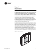
® Chapter 1 Overview The Tracker building automation system (BAS) is an energy management system for small- to medium-size buildings. The Tracker BAS controls heating, ventilating, and air conditioning (HVAC) equipment. It consists of a Tracker controller (Figure 1) and an optional PC workstation. The Tracker BAS can be operated by using either a Tracker controller or a PC workstation that is running Tracker PC Workstation software.
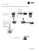
® Chapter 1 Overview Figure 2. Example Tracker building automation system (models 12 and 24) on a network VariTrac or VariTrane zone dampers Voyager constant volume rooftop Interconnecting wiring (Comm5 link): single, twisted pair, shielded wire for twoway communication.
® Overview Figure 3. Example building automation system (water-source heat pump) on a network Tracer loop controller (for water-source heat pump) Tracer ZN510, ZN511, or ZN524 controller Analog inputs Binary inputs Binary outputs Voyager constant volume rooftop Interconnecting wiring (Comm5 link): single, twisted pair, shielded wire for twoway communication.
® Chapter 1 Overview Controller components The controller consists of a termination module, main module, and display module (Figure 4). Figure 4.
® Controller components Termination module The termination module (Figure 5) is a housing that provides a termination board and cable access for power, communications, and system input connections. Mounting holes enable it to be mounted on a wall or a recessed conduit box. The termination board accepts connections for power, communications, and system inputs. Figure 5.
® Chapter 1 Overview Main module The main module (Figure 6) is a housing that contains the main logic board and the Ethernet board. The main module can be “hot swapped”: it can be removed and installed without removing power from the termination module. When the main module is installed onto a powered termination module, it receives power and begins to operate automatically. The main logic board provides an Ethernet LAN port, a PC interface port, and a modem port.
® Controller components Display module The display module (Figure 7) is a housing that contains a printed circuit board, liquid crystal display (LCD) touch screen, and an alarm LED. The printed circuit board supports the LCD touch screen and the alarm LED. The touch screen provides the operator access to the user interface program. The display module can be “hot swapped:” it can be removed and installed without removing power from the main module.
® Chapter 1 Overview Model numbers Each controller is identified by a model number that provides information about the controller (Figure 8). Figure 8.
® Tracker controller specifications Tracker controller specifications Table 1 shows the specifications for the Tracker controller. Table 1.
® Chapter 1 Overview UCM maximum capacities for Tracker models 12 and 24 The Tracker model 12 and 24 controllers can control and monitor specific types and numbers of Trane unit control modules (UCMs) as specified in this topic.
® UCM maximum capacities for Tracker model WSHP UCM maximum capacities for Tracker model WSHP The Tracker model WSHP controller can control and monitor specific types and numbers of Trane unit control modules (UCMs) as specified in this topic. The supported UCMs are as follows: • • • Space Comfort Controllers (SCCs): the primary controller options are the Tracer ZN510, ZN511, and ZN524.
® Chapter 1 Overview Before installation Before beginning to install the Tracker controller, make sure that you have all the necessary controller components and that they are undamaged. Also, take steps to protect components until they are needed. IMPORTANT Before you install the Tracker hardware, review this guide and other Tracker support literature and create an installation plan. Verify the shipment When the shipment arrives at the job site, carefully unpack the carton.
® After installation After installation After installing the Tracker hardware, use the post-installation checklist (Table 4) to verify that all installation procedures were completed. Table 4. Tracker controller post-installation checklist Inspect shipment upon receipt Verify communication wiring _____ Verify that the shipment is complete. _____ Verify that wiring complies with specifications. _____ Inspect the controller and accessories to verify that there has been no shipping damage or loss.
® Chapter 1 Overview FCC compliance The Tracker controller generates, uses, and radiates radio frequency energy and if not installed and used in accordance with the instruction manual, may cause interference to radio and television reception.
® Chapter 2 Termination module mounting After unpacking and inspecting the shipment, mount the termination module. The mounting process for the termination module consists of selecting a location and mounting the module. This chapter provides information and procedures that enable you to mount the termination module. Select a location for the controller When selecting a location for the Tracker controller: • • • • Select a location that is in a clean, non-corrosive, indoor environment.
® Chapter 2 Termination module mounting Verify location conformance to controller dimensions and clearances Verify that the selected location provides enough space to accommodate the controller (Figure 9) and its minimum clearances (Figure 10 on page 17): • • • The top clearance allows for ventilation and conduit entry. The bottom clearance allows for PC cable interface clearance. The front clearance allows for operation and service access. Figure 9. Dimensions Top view 10.25 in. (26.04 cm) 2.75 in.
® Select a location for the controller Figure 10. Minimum clearances 12 in. (30 cm) 12 in. (30 cm) 12 in. (30 cm) 36 in. (91 cm) Front 12 in. (30 cm) BMTK-SVN01D-EN Back 54 in. Distance (1.
® Chapter 2 Termination module mounting Verify location conformance to optimal touch screen viewing angles Verify that the height and location enable the user to view the touch screen at the optimal viewing angles (Figure 11). Figure 11.
® Mount the termination module Mount the termination module After selecting a suitable location for the Tracker controller, mount the termination module. Mounting consists of securing the termination module to a wall or a 2 in. × 4 in. recessed conduit box (mounted vertically or horizontally) or a 4 in. × 4 in. recessed conduit box (several European electrical box sizes are also usable) and installing electrical conduit (optional).
® Chapter 2 Termination module mounting Securing the termination module to a wall 1. Mark the location of the two mounting holes on the wall. 2. Set the termination module aside and drill mounting holes. 3. Secure the termination module to the wall with the supplied hardware (#10 × 1 in. screw with plastic anchor). Securing the termination module to a conduit box 1. Remove the screws from the conduit box. 2.
® Mount the termination module Installing electrical conduit Use the conduit openings on the top of the Tracker termination module to supply power or communication wires to the controller. If the controller is mounted on a wall, you must use electrical conduit. If the controller is mounted to a conduit box through which power, input/ output, and communications are supplied, you do not need to use electrical conduit. IMPORTANT The 24 Vac wire conduit may not contain input/output or communication wires.
® Chapter 2 Termination module mounting 22 BMTK-SVN01D-EN
® Chapter 3 Termination board wiring After mounting the termination module, wire the termination board. The wiring process consists of wiring the termination board to 24 Vac power, inputs, outputs, and UCMs. This chapter provides information and procedures that enable you to wire the termination board. Figure 14 on page 24 shows all field wiring connections.
® Chapter 3 Termination board wiring Figure 14.
® Wire 24 Vac power Wire 24 Vac power After the termination module is mounted in the selected location, wire 24 Vac power to the termination board. Table 5 shows the specifications for power wiring. Table 5. Power wiring specifications 24 Vac power terminals 24 Vac TB1-1, TB1-2, Earth ground TB1-3 Description Power input 24 Vac nominal (19–30 Vac), 50/60 Hz, 1 phase 40 VA minimum, class 2 transformer required Wire specifications Trane recommends 18 AWG (1.02 mm2) wire and metal conduit.
® Chapter 3 Termination board wiring Wire optional inputs and outputs The Tracker controller provides input and output terminals as follows: • • • • Input for an optional priority shutdown device Input for an optional utility pulse meter Input for an optional outdoor air temperature sensor Output terminal for an optional alarm relay Refer to Table 6 for input and output wire specifications, and to the termination board wiring diagram in Figure 14 on page 24 for wiring all inputs and outputs. Table 6.
® Wire optional inputs and outputs Wire the alarm relay Wire the alarm relay to the termination board output. CAUTION Avoid Equipment Damage! Use a dedicated power transformer for this output. Failure to do so will damage the main module, if the alarm output is powered from the Tracker 24 Vac input (TB-1 and TB-2) and the circuit shorts to ground. 1. Route input wires into the termination module through a conduit opening (Figure 12 on page 19) or the conduit box. 2.
® Chapter 3 Termination board wiring Wire the utility pulse meter Wire the utility pulse meter to the termination board input. 1. Route input wires into the termination module through a conduit opening (Figure 12 on page 19) or the conduit box. 2. Connect the wires to the METER INPUT terminals on the termination board (Figure 14 on page 24). 3. Connect the other end of the wires to the pulsed-output contacts of the electrical meter.
® Wire the UCMs Wire the UCMs The Comm5 communication link connects unit control modules (UCMs) to the Tracker termination module. Each controller has one Comm5 communication link. This topic includes information and procedures for wiring a UCM to a termination module: Note: Do not exceed the maximum number of UCMs that can communicate on a Tracker controller (see “UCM maximum capacities for Tracker models 12 and 24” on page 10 for details).
® Chapter 3 Termination board wiring Table 7. Trane-approved wire suppliers Supplier Connect-Air International Phone: 1-800-247-1978 FAX: 1-253-813-5699 Web: www.connect-air.com Windy City Wire Phone: 1-800-379-1191 FAX: 1-708-493-1380 Web: www.smartwire.com Number of pairs Cable type Details Catalog number Level 4 22 AWG (0.643mm2) 1 Shielded plenum UL type CMP W221P-2002 Level 4 22 AWG (0.643mm2) 1 Shielded non-plenum UL type CM W221P-1003 Level 4 22 AWG (0.
® Wire the UCMs Table 8. Specifications for Echelon Level 4 compliant cables Specification Value dc resistance (Maximum resistance of a single copper conductor regardless of whether or not it is solid or stranded and regardless of whether or not it is metal coated.) 18.
® Chapter 3 Termination board wiring UCM wiring configurations The Tracker UCM Comm5 communication-link wiring must be installed in a daisy-chain configuration (Figure 15 on page 32 and Figure 16 on page 33). Figure 15. Daisy-chain configuration for UCM communication-link wiring (preferred configuration) Tracker Controller Trane UCM Trane UCM Trane UCM Figure Note: Maximum wire length for daisy-chained wiring is 4593 ft (1400 m).
® Wire the UCMs Figure 16. Daisy-chain configuration for UCM communication-link wiring with Tracker controller in middle of link Tracker Controller Trane UCM Trane UCM Trane UCM Trane UCM Trane UCM Trane UCM Figure Note: • Maximum wire length for daisy-chained wiring is 4593 ft (1400 m) unless a Comm5 repeater is used.
® Chapter 3 Termination board wiring Termination resistor placement for Comm5 links Install one 105 Ω resistor across the communication link terminals of the device at the beginning of the daisy chain, which is typically a Tracker controller. Then install a second 105 Ω resistor across the communication terminals at the last UCM on each link. See Figure 17 on page 35 for an example of a link that begins with a Tracker controller.
® Wire the UCMs Figure 17. Daisy-chain termination resistor placement Tracker termination board TB1 1 Legend = Twisted pair, shielded wire per Trane specifications = Shield ground = Termination resistor 2 = Shield termination = Figure note 3 4 5 6 7 8 (Last device on the link) 9 Comm5 device B Comm5 device A B A B 10 A B 11 A 13 1 1 14 COMM 12 15 2 Splice 3 Figure Notes: 1 105 Ω termination resistor 2 Shield must be cut back and taped at last unit controller.
® Chapter 3 Termination board wiring Figure 18.
® Wire the UCMs Wire supported UCMs Wire the supported UCMs to the Tracker termination board. When installing communication wire: • • Keep the polarity consistent throughout the site. Although Comm5 is not polarity sensitive, consistency will improve serviceability. Strip away a maximum of 2 inches (50 mm) of the outer conductor and foil shield when splicing or terminating shielded wire. IMPORTANT Use extreme care when stripping away the outer conductor and foil shield.
® Chapter 3 Termination board wiring • • The link repeater is limited to 60 devices on either side of the link (120 devices total). The link repeater requires an earth ground. The installer should be aware of this before making power connections. Recommended shield connections are shown in Figure 19. Figure 20 on page 39 shows a daisy-chain repeater connection.
® Wire the UCMs Figure 20.
® Chapter 3 Termination board wiring 40 BMTK-SVN01D-EN
® Chapter 4 Main module mounting After mounting and wiring the termination module, attach the main module to the termination module. This chapter provides information and procedures that enable you to mount the main module. Note: The Tracker controller ships with the display module assembled to the main module. If those two modules are assembled, performing this procedure also mounts the display module.
® Chapter 4 Main module mounting Figure 21.
® Chapter 5 Display module mounting After mounting the main module, attach the display module to the main module. This chapter provides information and procedures that enable you to mount the display module. Note: The Tracker controller ships with the display module assembled to the main module. If those two modules are assembled, you need only to perform the main module mounting procedure (Chapter 4, “Main module mounting”).
® Chapter 5 Display module mounting Figure 22.
® Display module mounting Figure 23.
® Chapter 5 Display module mounting 46 BMTK-SVN01D-EN
® Chapter 6 PC workstation wiring The Tracker controller connects to a PC workstation with a direct connection cable, an internal modem, or an Ethernet connection. Verify PC workstation specifications Verify that the PC conforms to the minimum specifications listed on the insert in the CD jewel case and that the Tracker PC workstation software is installed.
® Chapter 6 PC workstation wiring IMPORTANT Do not use a standard phone cable for a direct connection. The RJ-12 cable is a 6-wire straight-through cable. Failure to comply will cause the Tracker controller to malfunction. IMPORTANT The maximum allowable length of the RJ-12 cable is 50 ft (15 m). Failure to comply may cause the Tracker controller to malfunction. 1. Locate the RJ-12 cable and the appropriate adapter. 2.
® Direct connection to PC workstation Figure 25.
® Chapter 6 PC workstation wiring Modem connection to PC workstation To make a modem connection between the controller and a PC workstation, you need an RJ-11 cable (standard telephone cable). Note: The Trane Company reserves the right to support only selected modems for the Tracker PC workstation. This ensures proper operation of the Tracker software and makes troubleshooting easier, if a communication failure occurs. Modem specifications are subject to change.
® Modem connection to PC workstation Figure 26.
® Chapter 6 PC workstation wiring Ethernet connection to PC workstation Connecting over an existing LAN To make an Ethernet LAN connection between the Tracker controller and a Tracker PC Workstation through an existing customer LAN, you need two CAT 5 patch cables. 1. Connect one end of the first CAT 5 patch cable to the RJ-45 Ethernet port on the bottom side of the Tracker controller (Figure 27 on page 52). 2. Connect the other end of the cable to an RJ-45 Ethernet wall jack near the controller. 3.
® Ethernet connection to PC workstation Connecting through a hub To make an Ethernet connection between the Tracker controller and a Tracker PC Workstation through a hub, you need two CAT 5 patch cables. 1. Connect one end of the first CAT 5 patch cable to the RJ-45 Ethernet port on the bottom side of the Tracker controller (Figure 27 on page 52). 2. Connect the other end of the cable to an RJ-45 Ethernet port on the hub. 3.
® Chapter 6 PC workstation wiring Connecting with one cable To make an Ethernet connection between the Tracker controller and a Tracker PC Workstation using one cable, you need one CAT 5 crossover cable. 1. Connect one end of the CAT 5 crossover cable to the RJ-45 Ethernet LAN port on the bottom side of the Tracker controller (Figure 29). 2. Connect the other end of the cable to the RJ-45 Ethernet LAN port on the Tracker PC Workstation. Figure 29.
® Chapter 7 Troubleshooting Troubleshooting components Light-emitting diodes (LEDs) and service pin buttons are used for troubleshooting the Tracker system. LEDs The LEDs on the Tracker controller main logic board and display module show central processing unit (CPU) status and traffic on the Comm5 communication link, the Ethernet module, and the EIA-232 connection. Figure 30 shows the location of the main logic board LEDs; Table 11 on page 57 provides a description of them.
® Chapter 7 Troubleshooting Figure 30.
® Troubleshooting components Table 11. Tracker main logic board LEDs LED name LED number HI TX LED6 Green Flashes when the main module attempts to communicate with the display module. The main module attempts to communicate with the display module even when the display module is not installed. With no display module installed, the LED flashes every two seconds. HRT LED5 Green Shows the status (heart beat) of the CPU. This LED is on continuously while the controller boots up.
® Chapter 7 Troubleshooting Table 13. Main logic board service pin buttons and jumper Service pin buttons/jumper S1 Function This service pin is the reset button. Pressing S1 reboots the controller. It starts the same operation as does rebooting the controller from either the controller or the PC software. All RAM data is permanently lost. Note: Before pressing this button, attempt to restart the controller by cycling power; this method retains the RAM image.
® Symptom/action troubleshooting Symptom/action troubleshooting Table 14 provides a list of symptoms that indicate a problem in the Tracker system. For each symptom, the table provides one or more actions that you can perform in an attempt to resolve the problem. Table 14. Symptom/action troubleshooting Symptom Action Tracker controller does not communicate by modem. • Verify that the telephone cable is connected to the PC modem port (Figure 24 on page 48).
® Chapter 7 Troubleshooting Table 14. Symptom/action troubleshooting (Continued) Symptom Tracker alarm output is not working as expected. Action • Confirm proper wiring of the alarm relay output. Consult the post-installation checklist (Table 18 on page 70) for details. • Initiate the BOP self test from the display module. Note: The binary output is for alarm notification only. There must be an unacknowledged alarm present of the proper severity to actuate the alarm output.
® Symptom/action troubleshooting Table 14. Symptom/action troubleshooting (Continued) Symptom Tracker controller displays the wrong date. Action • Verify if the electrical power has been off for more than 1 week (the actual time varies depending on storage temperature). • Verify that jumper pin J1 on the main module is in place.
® Chapter 7 Troubleshooting 62 BMTK-SVN01D-EN
® Chapter 8 Maintenance The only maintenance necessary for the controller is to occasionally clean and calibrate the touch screen. Cleaning the touch screen To clean the touch screen, wipe it off with a non-abrasive cloth. For more aggressive cleaning, use low-pressure compressed air to blow off the surface and then wipe it off with a non-abrasive cloth. To clean fingerprints from the touch screen, lightly spray it with a mild glass cleaner.
® Chapter 8 Maintenance 64 BMTK-SVN01D-EN
® Appendix A Installation checklists Required supplies Table 15 lists the supplies required for all Tracker installations. Table 15. Required supplies checklist ; Wiring installation Item 24 Vac 18 AWG (1.02 mm2) wire recommended 24 Vac, 40 VA minimum transformer Comm Communication wire (see Table 7 on page 30 and Table 8 on page 31 for specifications) Optional supplies Table 16 lists the supplies that may or may not be necessary, depending on the Tracker installation. Table 16.
® Appendix A Installation checklists Comm5 UCM identification and location Each UCM has a unique 12-digit identifier that serves as its address. The Tracker controller uses the address to communicate with the UCM. The installer must know the UCM addresses when assigning names to UCMs during setup. Use Table 17 to record the name, location, and ID of each UCM (SCCs, VariTrac CCPs, and I/O modules) connected to the Comm5 link. The 12digit identifier is on a sticker attached to the UCM.
® Comm5 UCM identification and location Table 17.
® Appendix A Installation checklists Table 17.
® Pre-installation wiring notes Pre-installation wiring notes The wiring for the Tracker system will have been completed prior to Tracker installation. All Tracker wiring conforms to the following guidelines: • • • • • BMTK-SVN01D-EN The Tracker controller receives 24 Vac from a dedicated power circuit. If not, the Tracker controller may malfunction. Each UCM receives 24 Vac from a dedicated power source. If not, the UCM may malfunction.
® Appendix A Installation checklists Termination module post-installation checklist Use Table 18 to verify that the circuits connected to the termination board on the termination module are wired correctly. Record test results in the “Actual value” column. Table 18. Termination module post-installation checklist Circuit 24 Vac TB1-1, TB1-2, TB1-3 Mandatory wiring Test Actual value Measure the voltage between TB1-1 and TB1-2. It must be 24 Vac nominal (19 Vac to 30 Vac).
® Termination module post-installation checklist Table 19. Thermistor sensor electrical characteristics BMTK-SVN01D-EN Sensor resistance (ohms x 1000) Temperature (ºF) Temperature (ºC) –30 –34 241.1 –20 –29 170.1 –10 –23 121.4 0 –18 87.6 10 –12 63.8 20 –7 46.9 30 –1 34.5 40 4 26.2 50 10 20.0 60 16 15.3 70 21 11.9 77 25 10.0 80 27 9.3 90 32 7.3 100 38 5.8 110 43 4.7 120 49 3.8 130 54 3.0 140 60 2.5 150 66 2.
® Appendix A Installation checklists 72 BMTK-SVN01D-EN
® Appendix B Declaration of Conformity This appendix provides the Declaration of Conformity statement for the Tracker model 12, 24, and WSHP controllers. All Tracker models are currently CE certified.
® Appendix B Declaration of Conformity Declaration of Conformity Manufacturer’s Name: Manufacturer’s Address: Trane 4833 White Bear Parkway Saint Paul, Minnesota 55110 USA The manufacturer hereby declares that the product: Product Name: Product Number: Tracker model 12, 24, and water-source heat pump (WSHP) BMTK000AA0A110 BMTK000AA0A210 BMTK000AA0A510 BMTKKBBAA0A110 BMTKKBBAA0A210 BMTKKBBAB0A110 BMTKKBBAB0A210 BMTK000AB0A110 BMTK000AB0A210 BMTK000AB0A510 Conforms to the following standards or other
® Index Numerics 24 Vac power wiring, 25 A adapters for direct connection to PC, 47 alarm relay wire requirements, 26 wiring procedures, 27 analog input, 9 thermistor, general, 26 thermistor, wiring, 28 B binary input priority shutdown device input, wiring, 27 priority shutdown device, general, 26 utility pulse meter, general, 26 utility pulse meter, wiring, 28 binary output alarm relay, general, 26 alarm relay, wiring, 27 C cabinet specifications, 9 cable for direct connection to PC, 47 cable installat
Index E EIA-232 connection installing, 47 LEDs, 55 electrical conduit installation, 19, 21 electrical interference, 15 Ethernet communication port, 48 Ethernet connection to PC procedures, 52 I I/O modules maximum capacity per controller, 10, 11 I/O options, 26 installation after, 13 before, 12 checklists, 65–71 direct connection to PC, 47 electrical conduit, 19, 21 Ethernet LAN connection to PC, 52 modem connection to PC, 50 J jumper function, 58 general, 55 description, 6 mounting, 41–42 maintenance,
Index description, 37 limitations, 37 requirements, 37 wiring, 29 RJ-11 cable installation, 50 modem connection procedures, 50 PC communication port, 48 RJ-12 cable installation, 47 direct connection procedures, 48 parts specifications, 47 PC communication port, 48 RJ-45 Ethernet connection procedures, 52 S SCCs maximum capacity per controller, 10, 11 service pin buttons, 55, 58 shipment component verification, 12 inspect for damage, 12 Space Comfort Controllers (SCCs), 10, 11 specifications analog input,
Index wire Comm5, 29 requirements for alarm relay, 26 requirements for meter, 26 requirements for outdoor air temperature sensor, 26 requirements for priority shutdown device input, 26 specifications, 29 wiring 24 Vac, 25 alarm relay, 27 configurations for Comm5 UCM communication, 32 daisy-chain configuration, 32, 33 I/O terminals, 26 outdoor air temperature sensor, 28 PC connection, 47 priority shutdown device input, 27 procedures for UCMs, 37 repeaters, 29 termination board, 23–40 UCMs, 29–40 utility pul
® Trane A business of American Standard Companies www.trane.com For more information, contact your local Trane office or e-mail us at comfort@trane.com Literature Order Number BMTK-SVN01D-EN File Number SV-ES-BAS-BMTK-SVN-01D-EN-0204 Supersedes SV-ES-BAS-BMTK-SVN-01C-EN May 2003 Stocking Location Inland Trane has a policy of continuous product and product data improvement and reserves the right to change design and specifications without notice.