
user manual

®
Chapter 2 Termination module mounting
16 BMTK-SVN01D-EN
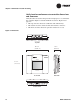
Verify location conformance to controller dimensions
and clearances
Verify that the selected location provides enough space to accommodate
the controller (Figure 9) and its minimum clearances (Figure 10 on
page 17):
• The top clearance allows for ventilation and conduit entry.
• The bottom clearance allows for PC cable interface clearance.
• The front clearance allows for operation and service access.
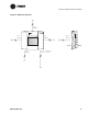
Figure 9. Dimensions
Front view
Side view
8.75 in.
(22.38 cm)
2.75 in.
(6.99 cm)
10.25 in.
(26.04 cm)
Top view
Bottom view