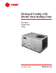
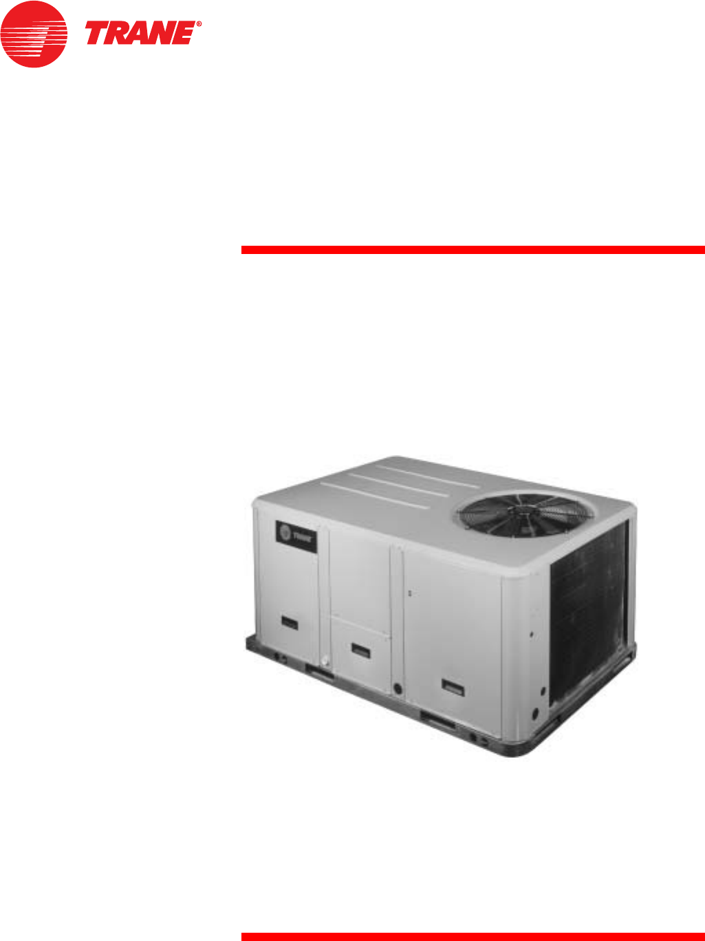
Packaged Cooling with Electric Heat Rooftop Units Precedent™ TSC060-120 50 Hz November 2003 RT-PRC016-EN
Introduction Precedent™ . . . The same Trane quality... with added flexibility. Precedent is a flexible line of packaged units that covers a wide variety of applications. ReliaTel™ microprocessor controls provide superior flexibility for the simplest to the most sophisticated applications. In addition to controls, Precedent offers many other outstanding features and option choices. © 2003 American Standard Inc. All rights reserved.
Contents RT-PRC016-EN Introduction 2 Features and Benefits 4 Application Considerations 9 Selection Procedure 10 Model Number Description 12 General Data 13 Performance Data 14 Zone Controls 33 Electrical Data 34 Jobsite Connections 35 Dimensional Data 36 Weights 44 Mechanical Specifications 45 3
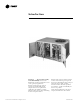
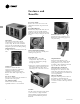
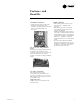
Features and Benefits Easy Access Panels Remove two screws for access to the standardized internal components and wiring. Easy-Adjust Idler Arm With the Easy-Adjust Idler Arm, the belt and sheaves can be quickly adjusted without moving the mounted fan motor. The result is a major savings in time and money. Patented Condenser Coil Precedent boasts a patented 1+1+1 Hybrid coil, permanently gapped for easy of cleaning.
Features and Benefits Standardized Components • Components are placed in the same location on all Precedent™ units. Familiarize yourself with one Precedent and you are familiar with every Precedent. Flexible Applications • Only two roof curbs for the 5-10 ton Precedent line. . .simplifies curb selection. • ReliaTel microprocessor controls to meet either the simple or the more complex application. • Airflow is outstanding.
Features and Benefits • Eliminates the need for field-installed components with its built-in antishort-cycle timer, time delay relay and minimum ‘’on’’ time controls. These controls are factory tested to assure proper operation. Micro Controls Several years ago, Trane was the first to introduce microprocessor controls into the Light Commercial Market. That design, along with immeasurable experience, has provided the technology for Trane’s secondgeneration ReliaTel™ microprocessor controls.
Features and Benefits Factory-installed Options Hinged Access Doors These doors permit easy access to the filter, fan/heat, and compressor/control sections. They reduce the potential roof damage from screws or sharp access door corners. Economizer Equipped with either dry bulb, reference or comparative enthalpy sensing, this feature provides free cooling as the outdoor temperature and/or humidity decreases. Economizers, correctly installed, offer a valuable energy savings.
Features and Benefits Quality And Reliability Testing • All Precedent™ designs were rigorously rain tested at the factory to ensure water integrity. • Actual shipping tests were performed to determine packaging requirements. Units were test shipped around the country to determine the best packaging. • Factory shake and drop tests were used as part of the package design process to help assure that the unit arrives at the job site in top condition.
Application Considerations Application of this product should be within the cataloged airflow and cooling considerations. Low Ambient Cooling The Precedent™ line features, with ReliaTel™ microprocessor controls, low ambient cooling down to 18°C (0°F). Contact your local Trane Representative for more assistance with low ambient cooling applications. Barometric Relief This product line offers an optional barometric relief damper. for use in conjunction with economizer option.
Selection Procedure - SI Units Cooling Capacity Step 1 Calculate the building’s total and sensible cooling loads at design conditions. Use the Trane calculation methods or any other standard accepted method. Factors used in unit selection: A Total Cooling Load: 16.7 kW B Sensible Cooling Load: 11.7 kW Step 3 In order to select the correct unit which meets the building’s requirements, the fan motor heat must be deducted from the gross cooling capacity.
Selection Procedure - IP Units Cooling Capacity Step 1 Calculate the building’s total and sensible cooling loads at design conditions. Use the Trane calculation methods or any other standard accepted method. Factors used in unit selection: A Total Cooling Load: 59 MBh B Sensible Cooling Load: 40 MBh Step 3 In order to select the correct unit which meets the building’s requirements, the fan motor heat must be deducted from the gross cooling capacity.
Model Number Description T S C 060 A D R O 1 2 3 4,5,6 7 8 9 10 11 12,13 14 15 16 17 Digit 1 - Unit Function T = DX Cooling Digit 2 - Efficiency S = Standard Efficiency Digit 3 - Airflow C = Convertible Digits 4,5,6 - Nominal Gross Cooling Capacity (MBh) kW Tons 060 = 17.6 5 072 = 21.1 6 090 = 26.4 7.5 102 = 29.9 8.5 120 = 35.
General Data Table GD - 1 — General Data Cooling Performance 1 Gross Capacity - kW (MBh) COP (EER)2 Nominal Airflow - m3/h (cfm) Rated Airflow - m3/h (cfm) Net Capacity - kW (MBh) System Power - kW Compressor Number -Type Outdoor Sound Rating - dB 3 Outdoor Coil - Type Tube Size - in. OD Face Area - m2 (sq ft) Rows / FPI Indoor Coil - Type Tube Size OD - in. Face Area - m2 (sq ft) Rows / FPI Refrigerant Control Drain Connection No. / Size - in. Outdoor Fan - Type No. Used / Diameter - in. DriveType / No.
Performance Data Table PD-1 — Gross Cooling Capacities (kW) - TSC060AD - (SI) Ambient Temperature (C) m3/h Airflow 3060 3400 3740 4080 Enter. Dry Bulb Temp (C) 24 27 30 33 24 27 30 33 24 27 30 33 24 27 30 33 30 35 40 45 Entering Wet Bulb Temperature (C) 16 19 22 16 19 22 16 19 22 16 19 22 TGC SHC TGC SHC TGC SHC TGC SHC TGC SHC TGC SHC TGC SHC TGC SHC TGC SHC TGC SHC TGC SHC TGC SHC 16.2 13.9 18.5 11.3 19.9 8.3 15.0 13.3 17.4 11.3 19.3 8.0 13.9 12.7 16.1 10.7 18.4 7.5 12.7 12.1 14.7 9.5 17.3 7.
Performance Data Table PD-2 — Gross Cooling Capacities (kW) - TSC072AD - (SI) Ambient Temperature (C) m3/h Airflow 3670 4080 4490 4900 Enter. Dry Bulb Temp (C) 24 27 30 33 24 27 30 33 24 27 30 33 24 27 30 33 30 35 40 45 Entering Wet Bulb Temperature (C) 16 19 22 16 19 22 16 19 22 16 19 22 TGC SHC TGC SHC TGC SHC TGC SHC TGC SHC TGC SHC TGC SHC TGC SHC TGC SHC TGC SHC TGC SHC TGC SHC 20.9 17.5 23.3 14.6 24.6 10.3 19.7 16.8 22.4 13.6 24.0 9.9 18.4 16.1 21.2 12.9 23.2 9.4 17.1 15.4 19.7 12.9 22.0 9.
Performance Data Table PD-3 — Gross Cooling Capacities (kW) - TSC090AD - (SI) Ambient Temperature (C) m3/h Airflow 4590 5100 5610 6120 Enter. Dry Bulb Temp (C) 24 27 30 33 24 27 30 33 24 27 30 33 24 27 30 33 30 35 40 45 Entering Wet Bulb Temperature (C) 16 19 22 16 19 22 16 19 22 16 19 22 TGC SHC TGC SHC TGC SHC TGC SHC TGC SHC TGC SHC TGC SHC TGC SHC TGC SHC TGC SHC TGC SHC TGC SHC 24.5 21.6 26.9 17.1 28.1 12.0 22.7 20.6 25.8 16.3 27.7 11.5 20.8 19.6 24.1 15.4 26.8 11.0 19.0 18.7 22.0 14.8 25.
Performance Data Table PD-4 — Gross Cooling Capacities (kW) - TSC102AD - (SI) m3/h Airflow 5200 5780 6360 6940 Enter. Dry Bulb Temp (C) 24 27 30 33 24 27 30 33 24 27 30 33 24 27 30 33 30 35 Ambient Temperature (C) 40 45 Entering Wet Bulb Temperature (C) 16 19 22 16 19 22 16 19 22 16 19 22 TGC SHC TGC SHC TGC SHC TGC SHC TGC SHC TGC SHC TGC SHC TGC SHC TGC SHC TGC SHC TGC SHC TGC SHC 28.0 24.3 31.5 19.5 33.4 14.1 26.0 23.3 30.0 18.7 32.5 13.5 23.9 22.2 27.8 17.7 31.3 12.9 21.6 21.6 25.4 17.3 29.
Performance Data Table PD-5 — Gross Cooling Capacities (kW) - TSC120AD - (SI) Ambient Temperature (C) m3/h Airflow 6120 6800 7480 8160 Enter. Dry Bulb Temp (C) 24 27 30 33 24 27 30 33 24 27 30 33 24 27 30 33 30 35 40 45 Entering Wet Bulb Temperature (C) 16 19 22 16 19 22 16 19 22 16 19 22 TGC SHC TGC SHC TGC SHC TGC SHC TGC SHC TGC SHC TGC SHC TGC SHC TGC SHC TGC SHC TGC SHC TGC SHC 31.9 28.6 35.3 22.8 37.2 15.9 29.6 27.4 33.6 21.7 36.5 15.4 27.1 26.2 31.0 20.5 35.2 14.8 24.6 24.6 28.4 19.9 33.
Performance Data Table PD-6 — Belt Drive Evaporator Fan Performance - TSC060AD - Downflow Configuration (SI) 25 3 m /h RPM 2720 3060 3400 3740 4080 706 773 840 909 CFM 2720 3060 3400 3740 4080 50 75 100 kW RPM kW RPM kW RPM kW 1.12 Nom kW Standard Motor & Low Static Drive 703 0.27 757 0.31 806 0.35 0.32 760 0.35 815 0.40 861 0.45 0.43 821 0.46 873 0.51 918 0.57 0.56 885 0.60 930 0.65 977 0.71 0.71 950 0.76 990 0.80 1034 0.
Performance Data Table PD-7 - Belt Drive Evaporator Fan Performance- TSC060AD - Horizontal Configuration - (SI) 25 m3/h 75 RPM kW RPM kW RPM kW 1.12 Nom kW Std Motor & Low Static Drive 707 0.26 774 0.31 837 0.37 778 0.36 840 0.41 897 0.48 850 0.48 908 0.54 961 0.60 923 0.63 978 0.69 1028 0.76 997 0.80 1049 0.87 1096 0.94 External Static Pressure (Pascals) 100 125 150 175 200 RPM kW RPM kW RPM kW RPM kW RPM kW 1.12 Nom kW Standard Motor & Drive 898 0.43 953 0.48 1001 0.54 1045 0.59 1087 0.65 953 0.
Performance Data Table PD-8 — Belt Drive Evaporator Fan Performance -TSC072AD - Downflow Configuration (SI) 25 m3/h CFM 3260 3670 4080 4490 4890 75 100 RPM kW RPM kW RPM kW RPM kW 1.12 Nom kW Standard Motor & Low Static Drive 573 0.25 630 0.30 548 0.26 602 0.31 656 0.37 584 0.33 635 0.38 682 0.45 569 0.35 621 0.42 670 0.47 715 0.54 612 0.45 660 0.51 706 0.58 749 0.64 External Static Pressure (Pascals) 125 150 175 200 225 250 RPM kW RPM kW RPM kW RPM kW RPM kW RPM kW 1.
Performance Data Table PD-9 — Belt Drive Evaporator Fan Performance -TSC072AD - Horizontal Configuration (SI) 25 m3/h 3260 3670 4080 4490 4890 50 100 RPM kW RPM kW RPM kW RPM kW 1.12 Nom kW Standard Motor & Low Static Drive 565 0.23 627 0.29 679 0.34 566 0.26 609 0.31 663 0.36 716 0.42 619 0.35 660 0.40 701 0.45 751 0.51 672 0.45 710 0.51 745 0.56 788 0.62 726 0.58 762 0.64 795 0.70 828 0.76 1.12 Nom kW Standard Motor & Drive CFM 275 RPM kW 3260 3670 4080 4490 4890 978 996 1020 1049 1081 0.76 0.
Performance Data Table PD-10 — Belt Drive Evaporator Fan Performance -TSC090AD - Downflow Configuration (SI) 25 m3/h CFM 4080 4590 5100 5610 6120 75 100 RPM kW RPM kW RPM kW RPM kW 1.50 Nom kW Standard Motor & Low Static Drive 701 0.47 699 0.53 743 0.59 703 0.61 747 0.68 789 0.74 713 0.69 755 0.77 797 0.85 836 0.92 771 0.88 809 0.96 848 1.06 885 1.14 External Static Pressure (Pascals) 125 150 175 200 225 RPM kW RPM kW RPM kW RPM kW RPM kW 1.50 Nom kW Standard Motor & Drive 750 0.54 794 0.60 834 0.
Performance Data Table PD-11 — Belt Drive Evaporator Fan Performance -TSC090AD - Horizontal Configuration (SI) 25 50 75 m3/h RPM kW RPM kW RPM kW 1.50 Nom kW Std Motor & Low Static Drive 4080 673 0.42 718 0.47 4590 702 0.51 738 0.56 773 0.62 5100 771 0.68 805 0.74 837 0.81 5610 842 0.89 873 0.96 903 1.03 6120 913 1.14 942 1.22 970 1.30 1.50 Nom kW Standard Motor & Drive CFM 4080 4590 5100 5610 6120 100 RPM kW 769 817 870 930 996 0.54 0.68 0.87 1.10 1.
Performance Data Table PD-12 — Belt Drive Evaporator Fan Performance -TSC102AD - Downflow Configuration (SI) 25 m3/h 75 100 RPM kW RPM kW RPM kW RPM kW 1.50 Nom kW Standard Motor & Low Static Drive 613 0.45 611 0.48 650 0.55 612 0.51 651 0.59 689 0.68 622 0.56 659 0.64 693 0.72 729 0.82 671 0.71 706 0.80 738 0.89 770 0.98 External Static Pressure (Pascals) 125 150 RPM kW RPM kW 655 688 724 764 804 0.54 0.64 0.76 0.92 1.09 695 725 759 795 834 0.62 0.73 0.86 1.01 1.
Performance Data Table PD-13 — Belt Drive Evaporator Fan Performance -TSC102AD - Horizontal Configuration (SI) m3/h 50 75 4620 5200 5780 6350 6930 RPM kW RPM kW RPM kW 1.50 Nom kW Std Mtr & Low Static Drive 646 0.50 616 0.51 654 0.57 693 0.64 675 0.68 711 0.75 743 0.82 735 0.89 770 0.97 799 1.04 796 1.14 828 1.23 857 1.31 m3/h 275 RPM kW 300 RPM kW 4620 5200 5780 6350 6930 956 999 1034 1063 1093 982 1026 1067 1098 1125 1.25 1.49 1.73 1.96 2.23 1.33 1.58 1.86 2.11 2.
Performance Data Table PD-14 — Belt Drive Evaporator Fan Performance -TSC120AD - Downflow Configuration (SI) 25 m3/h RPM kW 5440 6120 6800 7480 8160 741 803 0.95 1.21 m3/h 5440 6120 6800 7480 8160 External Static Pressure (Pascals) 100 125 150 RPM kW RPM kW RPM kW RPM kW RPM kW 2.24 Nom kW Standard Motor & Low Static Drive 718 0.72 754 0.82 731 0.81 764 0.90 797 0.99 715 0.81 747 0.90 782 1.01 814 1.11 844 1.21 773 1.04 803 1.14 834 1.24 864 1.36 894 1.48 833 1.31 861 1.42 887 1.52 916 1.64 945 1.
Performance Data Table PD-15 — Belt Drive Evaporator Fan Performance -TSC120AD - Horizontal Configuration (SI) 25 m3/h 5440 6120 6800 7480 8160 m3/h 5440 6120 6800 7480 8160 50 75 100 RPM kW RPM kW RPM kW RPM kW 2.24 Nom kW Standard Motor & Low Static Drive 691 0.67 730 0.75 771 0.84 729 0.84 761 0.91 792 0.99 829 1.08 802 1.13 833 1.22 860 1.29 890 1.38 876 1.49 905 1.58 931 1.67 955 1.75 950 1.91 977 2.02 1002 2.11 1025 2.
Performance Data Table PD-16 — Standard Motor & Sheave/Fan Speed (RPM) Unit 6 Turns Model No. Open TSC060AD N/A TSC072AD N/A TSC090AD N/A TSC102AD N/A TSC120AD N/A Factory set at 3 turns open 5 Turns Open 898 698 752 688 782 4 Turns Open 967 751 806 737 838 3 Turns Open 1036 806 860 786 894 2 Turns Open 1105 859 914 835 950 1 Turns Open 1174 913 968 885 1006 Closed 1243 967 1020 934 1062 Table PD-17 — Standard Motor & Low Static Drive Accessory Sheave/Fan Speed (RPM) Unit 6 Turns Model No.
Performance Data Table PD-21 — Static Pressure Drops Through Accessories - (Pascals) Unit Model No.
Performance Data Table PD-23 — Auxiliary Electric Heat Capacity (SI) Total2 Unit Model No. Unit Voltage TSC060AD 380-415/50/3 TSC072AD 380-415/50/3 TSC090AD 380-415/50/3 TSC102AD 380-415/50/3 TSC120AD 380-415/50/3 KW 7.5 / 9.0 10.9 / 13.0 14.4 / 17.2 11.3 / 13.5 16.9 / 20.2 22.6 / 26.9 11.3 / 13.5 16.9 / 20.2 22.6 / 26.9 16.9 / 20.2 22.6 / 26.9 16.9 / 20.2 22.6 / 26.9 33.9 / 40.4 No. Stages 2 2 2 1 2 2 1 2 2 2 2 2 2 2 Stage 1 Stage 2 KW 3.75 / 4.5 5.45 / 6.5 8.95 / 10.7 11.3 / 13.5 11.
Performance Data Table PD-24 — Air Temperature Rise Across Electric Heaters (Degrees C) kW 380V / 415V 07.5 / 09.0 10.9 / 13.0 11.3 / 13.5 14.4 / 17.2 16.9 / 20.2 22.6 / 26.9 33.8 / 40.4 Voltage 380-415/50/3 380-415/50/3 380-415/50/3 380-415/50/3 380-415/50/3 380-415/50/3 380-415/50/3 Stages 2 2 1 2 2 2 2 3400 m3/h TSC060AD 6.6 / 7.9 9.6 / 11.4 —12.6 / 15.1 ———- 4100 m3/h TSC072AD ——8.3 / 9.9 —12.4 / 14.8 16.5 / 19.7 —- 5100 m3/h TSC090AD ——6.6 / 7.9 —9.9 / 11.8 13.2 / 15.
Zone Controls Zone Sensors Zone Sensors are the building occupant’s comfort control devices for Precedent™ units with the ReliaTel control. The zone sensor offering operates with the Reliatel microprocessor Non-programmable manual auto changeover with digital LCD Display — Auto, heat, cool or off mode selection button. Auto or off fan bottom. Status indication LCD indicators — System on, heat, cool, or service.
Electrical Data Table ED-1 — Unit Wiring Standard Indoor Fan Motor Minimum Maximum Fuse Circuit Size Or Maximum Ampacitiy Circuit Breaker1 17.7 25 23.2 35 24.8 35 26.8 35 31.2 40 Unit Operating Voltage Range 342-456 342-456 342-456 342-456 342-456 Unit Model No. TSC060AD TSC072AD TSC090AD TSC102AD TSC120AD Oversized Indoor Fan Motor Minimum Maximum Fuse Circuit Size Or Maximum Ampacitiy Circuit Breaker1 17.7 25 24.2 35 26.5 35 28.5 35 31.2 40 Notes: 1.
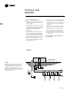
Jobsite Connections Zone Sensors — Typical Number Of Wires DISCONNECT SWITCH (BY OTHERS) ZONE SENSOR OR THERMOSTAT ROOFTOP UNIT A — Manual Changeover . . . . . . . . . . . . . . . . . 4 Manual/Auto Changeover . . . . . . . . . . . . . 5 Manual/Auto Changeover with Status Indication LED’s . . . . . . . . . . . . . 10 Programmable Night Setback with Status Indication LED’s . . . . . . . . . . . . . .
Dimensional Data TSC060 All dimensions are in inches/millimeters.
Dimensional Data TSC060 All dimensions are in inches/millimeters.
Dimensional Data TSC060 All dimensions are in inches/millimeters.
Dimensional Data TSC072-120 All dimensions are in inches/millimeters.
Dimensional Data TSC072-120 All dimensions are in inches/millimeters.
Dimensional Data TSC072-120 All dimensions are in inches/millimeters.
Dimensional Data TSC060 Options/Accessories All dimensions are in inches/millimeters.
Dimensional Data TSC072-120 Options/Accessories All dimensions are in inches/millimeters.
Weights Table W-1 - Maximum Unit and Corner Weights and Center of Gravity Dimensions (SI) Maximum Weights(2) (kg) Unit Model No. TSC060AD TSC072AD TSC090AD TSC102AD TSC120AD Shipping(2) 259 365 428 445 485 Net(2) 235 326 389 405 445 Corner Weights(1) (kg) A 75 107 131 133 147 B 56 83 101 106 115 C 48 58 67 72 81 Center of Gravity (mm) D 56 78 89 94 104 Length 790 970 970 990 990 Width 480 560 530 560 560 Notes: (1) Corner weights are given for information only.
Mechanical Specifications General The units shall be convertible airflow. The operating range shall be between 46°C and -18°C (115°F and 0°F) in cooling as standard from the factory for all units. All units shall be factory assembled, internally wired, fully charged with R-22, and 100 percent run tested to check cooling operation, fan and blower rotation, and control sequence before leaving the factory. Wiring internal to the unit shall be colored and numbered for simplified identification.
Mechanical Specifications Accessories/Options Electric Heaters — Field-installed electric heat modules shall be available for installation within basic unit. Electric heater elements shall be constructed of heavy-duty nickel chromium elements internally delta connected for 200 volt, wye connected for 380-415 volt. Staging shall be achieved through the unitary control processor (UCP). Each heater package shall have automatically reset high limit control operating through heating element contactors.
Mechanical Specifications High Pressure Cutout — Standard on all units. Hinged Access Doors — Sheet metal hinges are available factory-installed on the Filter/Evaporator, Supply Fan/Heat, and the Compressor/Control Access Doors. Black Epoxy Coated Condenser Coil — The coil provides corrosion protection to condenser coils for seacoast application. The protection is a factory-applied thermoset vinyl coating, bonded to normal aluminum fin stock.
Literature Order Number RT-PRC016-EN File Number PL-UN-000-RT-PRC016-EN-11-03 Trane A business of American Standard Companies www.trane.com Supersedes PL-UN-000-RT-PRC016-EN-10-03 Stocking Location 03-03 Webb/Mason 11-03 Electronic Only For more information, contact your local district office or e-mail us at comfort@trane.