Split System Heat Pumps Split System Heat Pumps TWA075A-TWA200B Air Handlers TWE050A-TWE200B 50 Hz January 2004 SSP-PRC002-EN
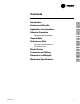
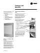
Introduction Split System Heat Pump Units . . . Designed With Your Needs In Mind. The Trane reputation for quality and reliability in air conditioning continues with the Odyssey™ family of light commercial split systems. Trane paid attention to your needs to make sure you get a system that will meet your job requirements every time...and at a competitive price. Designing the Details Filters The TWE050A, 075A, 100A and 100B air handlers are supplied with 1" (25.4 mm) throwaway filters as standard.
Contents Introduction Features and Benefits 2 Application Considerations 6 Selection Procedure 7 4 Model Number Description 8 9 General Data Performance Data 12 Cool and Heat Performance Fan Performance SSP-PRC002-EN Electric Power 12 24 31 Connection and Wiring 33 Dimension and Weights 39 Mechanical Specifications 52 3
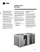
Features and Benefits Condensing Units Options TheTWA075A and 100A single compressor models feature single refrigeration circuitry, lowering job installation costs by requiring only one set of refrigerant lines.These units are ideal for the low cost, new construction jobs as well as renovation and replacement buildings. In addition, Odyssey includesTWA155B and 200B dual compressor units to give true stand-by protection; if one compressor fails, the second will automatically start-up.
Features and Benefits Odyssey air handler versatility is further increased by a complete line of accessories designed to match and install smoothly: • • • • • • • • Discharge Plenum and Grille Return Grille Subbase Electric Heaters High Static Evaporator Motor Isolators both Rubber-in-Shear and SpringType A Full Line ofThermostats OutdoorThermostat Odyssey Lowers Installation Costs Your installation costs are reduced with Odyssey.
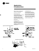
Application Considerations Application of this product should be within the catalogued airflow and performance considerations. Clearance Requirements The recommended clearances identified with unit dimensions should be maintained to assure adequate serviceability, maximum capacity and peak operating efficiency. Actual clearances which appear inadequate should be reviewed with the localTrane Representative.
Selection Procedure Cooling Capacity Step 1 — Calculate the building’s total and sensible cooling loads at design conditions. Step 2 — Size the equipment usingTable PD-1. Match the cooling loads at design conditions. Example:The following are the building cooling requirements a Electrical Characteristics: 380-415/50/3 b Summer Design Conditions: Entering Evaporator Coil: 80 DB/67 WB (27 DB/19 WB°C) Outdoor Ambient: 95°F (35° C) c Total Cooling Load: 75 MBh (22kW) d Sensible Cooling Load: 53 MBh (15.
Model Number Description Split System Heat Pump Model Nomenclature T W A 0 7 5 A D 0 0 D A 1 2 3 4 5 6 7 8 9 10 11 12 Digits 1, 2, 3 - Product Type Digit 8 - Electrical Characteristics TWA = Split System Heat Pump D = 380-415/3/50 Digits 4, 5, 6 - Nominal Gross Cooling Capacity (MBh) Digits 9, 10 - Factory - Installed Options 00 = No Options 0S = Black Epoxy Coated Coil 075 100 155 200 Digit 11- Minor Design Sequence D = Fourth = = = = 75 100 155 200 Digit 12- Service Digit
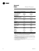
General Data (Heat Pumps) Table GD-1 — General Data — Heat Pumps Cooling Performance1 Gross Cooling Capacity, Btu (kW) Matched Air Handler, Btu (kW) Heat Pump Only2, Btu (kW) ARI Net Cooling Capacity3 System Power kW Heat Pump Only Power kW Heating Performance ARI Heating with Matched Air Handler HighTemperature Capacity, Btu (kW) LowTemperature Capacity, Btu (kW) Compressor Number Type No. Motors Motor HP (kW) Motor RPM ARI Sound Rating (Bels)4 System Data5 No. Refrigerant Circuits Suction Line, in.
General Data (Heat Pumps) Table GD-2 General Data — Heat Pumps Cooling Performance1 Gross Cooling Capacity, Btu (kW) Matched Air Handler, Btu (kW) Condensing Unit Only2, Btu (kW) ARI Net Cooling Capacity3 System Power kW Condensing Unit Power kW Heating Performance ARI Heating with Matched Air Handler HighTemperature Capacity, Btu (kW) LowTemperature Capacity, Btu (kW) Compressor Number Type No. Motors Motor HP Motor RPM, (kW) ARI Sound Rating (Bels)4 System Data5 No.
General Data (Air Handlers) Table GD-3 — General Data — Air Handlers TWE050A TWE075A TWE100A TWE100B System Data1 No. Refrigerant Circuits 1 1 1 2 Suction Line, in. (mm) OD 1.120 (28.4) 1.380 (35.0) 1.380 (35.0) 1.380 (35.0) Liquid Line, in. (mm) OD 0.38 (9.7) 0.50 (12.7) 0.50 (12.7) 0.50 (12.7) Indoor Coil — Type Plate Fin Plate Fin Plate Fin Plate Fin Tube Size, in. (mm) OD 0.375 (9.5) 0.375 (9.5) 0.375 (9.5) 0.375 (9.5) Face Area, sq. ft (m2) 5.00 (.47) 8.07 (.75) 11.18 (1.0) 11.18 (1.
Performance Data (System) Table PD-1 — Gross Cooling Capacities (MBh) TWA075A Heat Pump with TWE075A Air Handler (I-P) 85 Enter. Dry Bulb CFM 2250 2500 2750 3000 (°F) 61 67 95 73 61 67 Ambient Temperature (°F) Entering Wet Bulb (°F) 73 61 105 115 67 73 61 67 73 Total Sens. Total Sens. Total Sens. Total Sens. Total Sens. Total Sens. Total Sens. Total Sens. Total Sens. Total Sens. Total Sens. Total Sens. 75 78.1 61.6 86.4 51.4 95.4 35.1 75.4 60.3 83.4 50.1 91.9 33.9 72.3 58.8 79.
Performance Data (System) Table PD-2 — Gross Cooling Capacities (MBh) TWA100A Heat Pump with TWE100A Air Handler (I-P) 85 Enter. Dry Bulb CFM 3000 3325 3650 3975 (°F) 61 67 95 73 61 67 AmbientTemperature (°F) Entering Wet Bulb (°F) 73 61 105 67 115 73 61 67 73 Total Sens. Total Sens. Total Sens. Total Sens. Total Sens. Total Sens. Total Sens. Total Sens. Total Sens. Total Sens. Total Sens. Total Sens. 75 103.1 81.2 113.7 68.1 125.2 46.1 80 85 103.4 94.5 113.9 77.5 125.1 59.9 99.
Performance Data (System) Table PD-3 — Gross Cooling Capacities (MBh) TWA155B Heat Pump with TWE155B Air Handler (I-P) 85 Enter. Dry Bulb CFM 4500 5000 5500 6000 61 67 95 73 61 67 AmbientTemperature (°F) Entering Wet Bulb (°F) 73 61 105 67 115 73 61 67 73 (°F) Total Sens. Total Sens. Total Sens. Total Sens. Total Sens. Total Sens. Total Sens. Total Sens. Total Sens. Total Sens. Total Sens. Total Sens. 75 153.9 122.2 170.3 101.7 187.8 69.2 148.7 119.6 164.4 99.3 181.0 66.9 142.5 116.
Performance Data (System) Table PD-4 — Gross Cooling Capacities (MBh) TWA200B Heat Pump with TWE200B Air Handler (I-P) 85 Enter. Dry Bulb CFM 6000 6675 7350 8025 61 67 95 73 61 67 AmbientTemperature (°F) Entering Wet Bulb (°F) 73 61 105 67 115 73 61 67 73 (°F) Total Sens. Total Sens. Total Sens. Total Sens. Total Sens. Total Sens. Total Sens. Total Sens. Total Sens. Total Sens. Total Sens. Total Sens. 75 203.1 161.9 223.6 134.6 245.6 90.5 195.3 158.0 215.0 131.1 236.2 87.2 187.1 153.
Performance Data (TWA075A) Table PD-5 — Gross Cooling Performance (MBh) TWA075A Heat Pump Only (I-P) ODTemp Suction ReferenceTemperature °F °F 30 35 40 45 50 55 Head press PSIG 166 171 177 183 189 196 65 Cap. Btuh/1000 OD Unit KW 72.2 4.91 79.8 5.01 87.7 5.13 95.9 5.25 104.3 5.39 112.8 5.52 Head press PSIG 192 198 204 210 217 223 75 Cap. Btuh/1000 OD Unit KW 70.3 5.42 77.5 5.54 85.0 5.66 92.7 5.80 100.5 5.94 108.5 6.
Performance Data (TWA100A) Table PD-6— Gross Cooling Performance (MBh) TWA100A Heat Pump Only (I-P) ODTemp Suction ReferenceTemperature °F °F 30 35 40 45 50 55 Head press PSIG 164 169 174 179 185 191 65 Cap. Btuh/1000 OD Unit KW 99.4 6.39 109.5 6.53 120.0 6.67 130.9 6.83 142.2 6.99 153.9 7.16 Head press PSIG 188 193 199 204 210 216 75 Cap. Btuh/1000 OD Unit KW 95.1 7.06 104.5 7.21 114.4 7.36 124.8 7.52 135.5 7.69 146.6 7.
Performance Data (TWA155B) Table PD-7 — Gross Cooling Performance (MBh) TWA155B Heat Pump Only (I-P) ODTemp Suction ReferenceTemperature °F °F 30 Head press PSIG 35 40 45 50 55 165 170 176 182 188 194 142.4 9.59 157.4 9.80 173.0 10.02 189.2 10.26 205.9 10.52 222.8 10.78 65 Cap. Btuh/1000 OD Unit KW 75 Cap. Btuh/1000 OD Unit KW 219 225 232 238 245 252 85 Cap. Btuh/1000 OD Unit KW 133.3 11.75 147.0 12.01 161.1 12.27 175.6 12.54 190.3 12.82 205.3 13.
Performance Data (TWA200B) Table PD-8 — Gross Cooling Performance (MBh) TWA200B Heat Pump Only (I-P) ODTemp Suction ReferenceTemperature °F °F 30 Head press PSIG 35 40 45 50 55 173 179 185 191 198 205 196.4 12.94 215.5 13.25 235.3 13.58 255.8 13.93 276.9 14.30 298.5 14.69 65 Cap. Btuh/1000 OD Unit KW 75 Cap. Btuh/1000 OD Unit KW 226 233 240 247 254 262 85 Cap. Btuh/1000 OD Unit KW 177.5 15.95 194.5 16.32 212.3 16.71 230.8 17.12 249.9 17.56 269.5 18.
Performance Data (System) Table PD-9 — Gross Heating Capacities (MBh) TWA075A Heat Pump with TWE075A Air Handler At 2500 CFM (I-P) Outdoor Heating Capacity (Btu/1000) At Total Power in Kilowatts At Temperature (°F) Indicated Indoor Dry BulbTemperature 60 70 75 80 Indicated Indoor Dry BulbTemperature 60 70 75 80 -18 -13 -8 -3 2 7 12 17 22 27 32 37 42 47 52 57 62 67 72 33.0 34.1 35.6 37.5 40.0 42.8 46.2 50.0 54.4 59.2 64.5 69.9 75.7 81.8 88.3 95.1 102.0 109.0 116.3 28.7 30.4 32.4 34.8 37.7 41.1 44.
Performance Data (System) Table PD-10 — Gross Heating Capacities (MBh) TWA100A Heat Pump with TWE100A Air Handler At 3325 CFM (I-P) Outdoor Heating Capacity (Btu/1000) At Total Power in Kilowatts At Temperature (°F) Indicated Indoor Dry BulbTemperature 60 70 75 80 Indicated Indoor Dry BulbTemperature 60 70 75 80 -18 -13 -8 -3 2 7 12 17 22 27 32 37 42 47 52 57 62 67 72 20.4 31.4 39.0 45.5 51.8 57.9 64.1 70.4 76.9 83.6 90.7 97.6 104.6 112.0 119.5 127.1 134.8 142.6 150.7 37.3 41.8 46.3 50.8 55.6 60.
Performance Data (System) Table PD-11 — Gross Heating Capacities (MBh) TWA155B Heat Pump with TWE155B Air Handler At 5000 CFM (I-P) Outdoor Heating Capacity (BTUH/1000) At Total Power in Kilowatts At Temperature (°F) Indicated Indoor Dry BulbTemperature 60 70 75 80 Indicated Indoor Dry BulbTemperature 60 70 75 80 -18 -13 -8 -3 2 7 12 17 22 27 32 37 42 47 52 57 62 67 72 68.8 71.2 74.3 78.2 83.0 88.7 95.5 103.3 112.1 121.8 132.5 143.4 154.8 167.0 179.9 193.3 207.2 221.3 235.8 60.9 64.2 68.2 73.2 79.
Performance Data (System) Table PD-12 — Gross Heating Capacities (MBh) TWA200B Heat Pump with TWE200B Air Handler At 6675 CFM (I-P) Outdoor Heating Capacity (BTUH/1000) At Total Power in Kilowatts At Temperature (°F) Indicated Indoor Dry BulbTemperature 60 70 75 80 Indicated Indoor Dry BulbTemperature 60 70 75 80 -18 -13 -8 -3 2 7 12 17 22 27 32 37 42 47 52 57 62 67 72 42.4 68.2 81.5 93.1 104.2 115.2 126.6 138.2 150.3 162.9 176.1 189.2 202.8 216.9 231.9 247.4 263.2 279.3 295.9 79.1 86.2 93.8 101.
Performance Data (Air Handler) Table PD-13 — Evaporator Fan Performance — TWE050A (I-P) External Static Pressure (Inches of Water Column) CFM .10" .20" .30" .40" .50" .60" .70" .80" .90" 1.00" 1.10" RPM BHP RPM BHP RPM BHP RPM BHP RPM BHP RPM BHP RPM BHP RPM BHP RPM BHP RPM BHP RPM BHP 1400 — — — — 646 0.37 698 0.42 751 1500 — — 607 0.36 661 0.40 713 0.45 764 1600 — — 625 0.38 676 0.43 727 0.48 778 1700 601 0.35 648 0.40 696 0.44 744 0.49 792 1800 625 0.36 671 0.41 716 0.46 762 0.51 807 1900 642 0.
Performance Data (Air Handler) Table PD-15 — Evaporator Fan Performance TWE075A (I-P) External Static Pressure (In. Of Water Column) 0.10 0.20 0.30 0.40 0.50 0.60 0.70 0.80 0.90 1.00 1.10 RPM BHP RPM BHP RPM BHP RPM BHP RPM BHP RPM BHP RPM BHP RPM BHP RPM BHP RPM BHP RPM BHP CFM 2000 2125 2250 2375 2500 2625 2750 2875 3000 — — 443 0.44 489 — — 453 0.46 499 — — 463 0.49 510 — — 473 0.51 520 445 0.47 489 0.54 533 464 0.50 506 0.57 548 484 0.53 523 0.59 562 504 0.56 540 0.62 576 524 0.59 557 0.65 590 1.
Performance Data (Air Handler) Table PD-17 — Evaporator Fan Performance TWE100A, TWE100B (I-P) External Static Pressure (In. Of Water Column) 0.10 0.20 0.30 0.40 0.50 0.60 0.70 0.80 0.90 1.00 1.20 RPM BHP RPM BHP RPM BHP RPM BHP RPM BHP RPM BHP RPM BHP RPM BHP RPM BHP RPM BHP RPM BHP CFM 2600 2775 2950 3125 3300 3475 3650 3825 4000 1.5 HP Standard Motor and Low Static Drive 460 0.32 493 0.39 527 0.47 565 0.55 603 0.63 641 0.71 679 0.79 473 0.37 506 0.45 540 0.53 576 0.61 613 0.69 649 0.77 686 0.
Performance Data (Air Handler) Table PD-19 — Evaporator Fan Performance — TWE155B (I-P) External Static Pressure (Inches of Water Column) CFM 4000 4250 4500 4750 5000 5260 5500 5750 6000 .10" .20" .30" .40" .50" .60" .70" .80" .90" 1.00" 1.20" 1.40" RPM BHP RPM BHP RPM BHP RPM BHP RPM BHP RPM BHP RPM BHP RPM BHP RPM BHP RPM BHP RPM BHP RPM BHP 628 633 637 641 645 650 652 653 655 1.34 1.37 1.40 1.42 1.44 1.46 1.47 1.48 1.49 653 658 662 666 670 675 678 680 681 1.38 1.41 1.44 1.50 1.52 1.53 1.55 1.
Performance Data (Air Handler) Table PD-21— Evaporator Fan Performance TWE200B (I-P) External Static Pressure (In. Of Water Column) CFM 0.10 0.20 0.30 0.40 0.50 0.60 0.70 0.80 0.90 1.00 1.20 140 RPM BHP RPM BHP RPM BHP RPM BHP RPM BHP RPM BHP RPM BHP RPM BHP RPM BHP RPM BHP RPM BHP RPM BHP 5200 — — 5525 — — 5850 — — 6175 473 0.99 6500 492 1.12 6825 510 1.25 7150 528 1.38 7475 550 1.61 7800 572 1.83 3.0 HP Standard Motor and Low Static Drive 461 479 497 515 534 552 570 594 618 0.74 503 0.91 545 0.
Performance Data Table PD-23— Discharge Plenum And Grille Assembly Throw Distance — Air Handler — ft (m) Unit Louver Angle Deflection Position CFM m3/h Straight 20 40 55 1400 1600 1800 2000 2200 2100 2378 2718 3058 3398 3737 3568 38 (11.6) 42 (12.8) 46 (14.0) 48 (14.6) 51 (15.5) 49 (14.9) 24 (7.3) 31 (9.4) 37 (11.3) 43 (13.1) 50 (15.2) 38 (11.6) 22 (6.7) 26 (7.9) 29 (8.8) 33 (10.1) 36 (11.0) 31 (9.4) 18 (5.5) 20 (6.1) 22 (6.7) 24 (7.3) 25 (7.6) 27 (8.
Performance Data Table PD-25 — Auxiliary Electric Heat Capacity — Air Handler No. Stage 1 Total Total of kW Stages kW Input Btu Output kW Output kW Input Btu Output TWE050, 075,100 3.47 6.92 10.39 17.31 1 1 1 2 3.47 9.92 10.39 10.39 11,851 23,606 35,457 35,457 3.47 6.92 10.39 10.39 — — — 6.92 — — — 23,606 — — — 6.92 11,851 23,606 35,457 59,063 3.47 6.92 10.39 17.31 TWE075, 100A, 100 24.22 2 13.83 47,213 13.83 10.39 35,457 10.39 82,670 24.22 TWE155, 200 6.94 13.83 20.
Electrical Data Table ED-1— Electrical Characteristics — Motors — Air Handler Unit Model No. TWE050 TWE075 TWE100 TWE155 TWE200 Standard Fan Motor Amps Phase FLA 3 1.4 3 3.2 3 3.6 3 4.6 3 7.6 Volts 380/415 380/415 380/415 380/415 380/415 LRA 8.2 19.7 25.5 37.5 39.2 Oversized Fan Motor Amps Phase FLA 3 1.8 3 4.0 3 5.3 3 6.9 3 9.0 LRA 21.6 25.5 37.5 39.2 65.1 Table ED-2 — Unit Wiring — Air Handler Unit Model No.
Electrical Data Table ED-5— Unit Wiring With Electric Heat (Single Point Connection) — Air Handlers Heater Model No. BAYHTRL405A BAYHTRL410A BAYHTRL415A BAYHTRL425A BAYHTRL405A BAYHTRL410A BAYHTRL415A BAYHTRL425A BAYHTRL435A BAYHTRL405A BAYHTRL410A BAYHTRL415A BAYHTRL425A BAYHTRL435A BAYHTRM410A BAYHTRM420A BAYHTRM430A BAYHTRM450A BAYHTRM410A BAYHTRM420A BAYHTRM430A BAYHTRM450A Heater kW Rating1 3.47 6.92 10.39 17.31 3.47 6.92 10.39 17.31 24.22 3.47 6.92 10.39 20.78 24.22 6.94 13.83 20.78 34.62 6.94 13.
Jobsite Connections Wiring shown with dashed lines is to be furnished and installed by the customer. All customer- supplied wiring must be copper only and must conform to NEC and local electrical codes. Codes may require line of sight between disconnect switch and unit. NOTE: 1. When electric heater accessory is used single point power entry or dual point power entry is field optional. Single point power entry option is through electric heater only. TWA050/TWE050 Field Wiring: A — 3 power wires.
Typical Wiring (Heat Pump) Heat Pump — Single Compressor Typical unit wiring diagram. For specific wiring, see individual Service Facts.
Typical Wiring SSP-PRC002-EN (Heat Pump) 35
Typical Wiring (Heat Pump) Heat Pump — Dual Compressors Typical unit wiring diagram. For specific wiring, see individual Service Facts.
Typical Wiring SSP-PRC002-EN (Heat Pump) 37
Typical Wiring (Air Handler) Air Handler Typical unit wiring diagram. For specific wiring, see individual Service Facts.
Dimensional Data (Heat Pump) Figure DD-1 — TWA075 Heat Pump All dimensions are in inches and millimeters. Note 1 MINIMUM CLEARANCE FOR PROPER OPERATION IS 36 INCHES (914 MM) FROM WALLS, SHRUBBERY, PRIVACY FENCES, ETC.
Dimensional Data (Heat Pump) Figure DD-2 — 10 Ton TWA100A Heat Pump All dimensions are in inches and millimeters. Note 1 MINIMUM CLEARANCE FOR PROPER OPERATION IS 36 INCHES (914 MM) FROM WALLS, SHRUBBERY, PRIVACY FENCES, ETC.
Dimensional Data (Heat Pump) Figure DD-3 — TWA155B Heat Pump All dimensions are in inches and millimeters. Note 1 MINIMUM CLEARANCE FOR PROPER OPERATION IS 36 INCHES (914 MM) FROM WALLS, SHRUBBERY, PRIVACY FENCES, ETC.
Dimensional Data (Heat Pump) Figure DD-4 — TWA200B Heat Pump All dimensions are in inches and millimeters. Note 1 MINIMUM CLEARANCE FOR PROPER OPERATION IS 36 INCHES (914 MM) FROM WALLS, SHRUBBERY, PRIVACY FENCES, ETC.
Dimensional Data (Air Handler) Figure DD-5 — TWE050A Air Handlers All dimensions are in inches and millimeters. Notes: 1. Length, Width, and Height Dimensions do not include 1/2” (12.7mm) access panel depth. 2. Removable drain pan and attached drain connection may be installed on either end of unit in either the vertical or horizontal configuration. Plastic drain pan access plate on the end of unit opposite drain connection must be removed to slide drain pan out for cleaning.
Dimensional Data (Air Handler) Figure DD-6 — TWE075A Air Handler All dimensions are in inches and millimeters. Notes: 1. Length, Width, and Height Dimensions do not include 1/2” (12.7mm) access panel depth. 2. Removable drain pan and attached drain connection may be installed on either end of unit in either the vertical or horizontal configuration. Plastic drain pan access plate on the end of unit opposite drain connection must be removed to slide drain pan out for cleaning.
Dimensional Data (Air Handler) Figure DD-7— TWE100A Air Handler All dimensions are in inches and millimeters. Notes: 1. Length, Width, and Height Dimensions do not include 1/2” (12.7mm) access panel depth. 2. Removable drain pan and attached drain connection may be installed on either end of unit in either the vertical or horizontal configuration. Plastic drain pan access plate on the end of unit opposite drain connection must be removed to slide drain pan out for cleaning.
Dimensional Data (Air Handler) Figure DD-8— TWE100B Air Handler All dimensions are in inches and millimeters. Notes: 1. Length, Width, and Height Dimensions do not include 1/2” (12.7mm) access panel depth. 2. Removable drain pan and attached drain connection may be installed on either end of unit in either the vertical or horizontal configuration. Plastic drain pan access plate on the end of unit opposite drain connection must be removed to slide drain pan out for cleaning.
Dimensional Data (Air Handlers) Figure DD-9— TWE050A, 075A, 100A and TWE100B Air Handler All dimensions are in inches and millimeters. Table DD-1 — Air Handler Dimensions — in. (mm) Model No. TWE050A TWE075A TWE100A TWE100B SSP-PRC002-EN AA 35 5/8 (905) 45 1/8 (1146.2) 61 1/8 (1552.6) 61 1/8 (1552.6) AB 12 1/16 (306.4) 16 (406.4) 16 (406.4) 16 (406.4) AC 1 5/8 (41.3) 1 11/16 (42.9) 1 11/16 (42.9) 1 11/16 (42.9) AD 32 1/4 (819.2) 41 15/16 (1065.2) 57 15/16 (1471.6) 57 15/16 (1471.6) AE 2 15/16 (74.
Dimensional Data (Air Handler) Figure DD-10— TWE155B Air Handler All dimensions are in inches and millimeters. Notes: 1. Length, Width, and Height Dimensions do not include 1/2” (12.7mm) access panel depth. 2. Removable drain pan and attached drain connection may be installed on either end of unit in either the vertical or horizontal configuration. Plastic drain pan access plate on the end of unit opposite drain connection must be removed to slide drain pan out for cleaning.
Dimensional Data (Air Handlers) Figure DD-11 — TWE200B Air Handler All dimensions are in inches and millimeters. Notes: 1. Length, Width, and Height Dimensions do not include 1/2” (12.7mm) access panel depth. 2. Removable drain pan and attached drain connection may be installed on either end of unit in either the vertical or horizontal configuration. Plastic drain pan access plate on the end of unit opposite drain connection must be removed to slide drain pan out for cleaning.
Dimensional Data (Air Handlers) Figure DD-12— TWE155B and 200B Air Handlers All dimensions are in inches and millimeters. Table DD-2 — Air Handler Dimensions — in. (mm) Model No. TWE155B TWE200B A 77 1/4 (1962.2) 89 1/4 (2267) B 1 3/16 (30.2) 1 11/16 (42.9) C 48 (1219.2) 50 13/16 (1290.6) D 11 7/16 (290.5) 11 1/2 (292.1) E 18 (457.2) 20 1/8 (511.2) F 3 3/8 (85.7) 3 1/16 (77.8) G 35 1/16 (890.6) 39 1/8 (993.8) H 73 7/8 (1876.4) 82 7/8 (2105) J 3 3/4 (95.3) 4 9/16 (115.
Dimensional Data (Accessories) Figure DD-13— Electric Heater for TWE050, 075, 100 Air Handlers All dimensions are in inches and millimeters.
Mechanical Specifications Heat Pumps General Unit shall be assembled on heavy gauge steel mounting/lifting rails and shall be weather proofed. Unit shall include a hermetic scroll or reciprocating compressor(s), plate fin condenser coil, fans and motors, controls, and holding charge of nitrogen. Operating Range shall be between 115° F (46°C) and 50°F (10°C) in cooling as standard from factory. Unit shall be UL 1995 listed and rated in accordance with ARI Standard 340/360.
Mechanical Specifications Condenser Coil Guard — Metal grille with PVC coating shall be provided to alleviate coil damage. Black Epoxy Coated Condenser Coil — This factory installed option is designed to provide corrosion protection of air cooled condenser coils for seacoast application. The black epoxy coil protection is a factory applied thermoset vinyl coating, bonded to normal aluminum fin stock.
Trane An American Standard Company www.trane.com For more information contact your local office or e-mail us at comfort@trane.com Literature Order Number SSP-PRC002-EN File Number PL-UN-SSP-PRC002-EN-0104 Supersedes SS-PRC002-EN 1103 Stocking Location Electronic Only Since Trane has a policy of continuous product and product data improvement, it reserves the right to change design and specifications without notice.